CS 184: COMPUTER GRAPHICS
PROBLEM # 1:
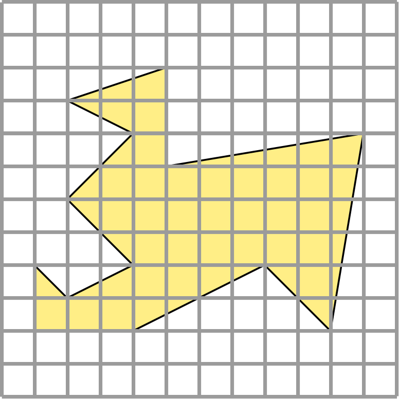
Fill in all pixels "owned" by the outlined polygon; focus on the "boundary pixels."
= = = = >
|

|
PROBLEM # 2:
Suggest an
effective rendering / shading
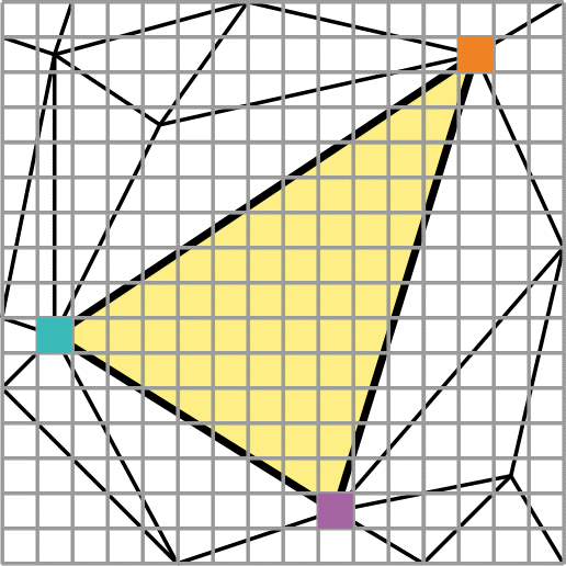
technique to set all the pixels colors for the yellow triangle (with
its corner colors
specified). = = >
|

|
PREVIOUS
< - - - - > CS
184 HOME < - - - - > CURRENT
< - - - - > NEXT
Lecture #8 -- Mon 2/14/2011.
From last lecture: PROBLEM #1: First figure out: What pixels are owned by the yellow polygon?
Then we need to find a method to set all pixels in memory with high efficience.
Sweeping Scan-line Approach -- Actual Process and Data Structures.
For now, we do this one polygon at a time. (not explained well enough in [Shirley]).
Datastructures:
-- Scene Graph -- Display List -- Edge Table
-- Active Edge List.
Preprocessing:
-- Bucket-sort (in y) all polygon edges (by their lower vertex) into the Edge Table.
Process the scan-line buckets from bottom to top.
-- Inserting
edges into scan-line buckets (details)
Scan-line Processing:
-- For the current swath of pixels, update the Active Edge List of all edges that cross the current scan line.
-- Details
of scan-line processing on active edge list
-- Turn on pixels that have their sampling points on active "inside" spans.
(For convenience we chose
the pixel sampling point to be the lower left corner, thus avoiding to
have to add/subtract 0.5 all the time.)
Now, regarding PROBLEM #2:
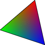
Gouraud Shading (= color interpolation between vertices)
In addition to the above, let's now assume that the polygon to be shaded is just a simple triangle.
It is normally a good idea to break complicated polygons into
triangles, then you know what you have got; different renderers may do
different (and sometimes strange) things to concave, or non-planar
polygons.
However, it is still important to understand the winding number
paradigm and to use it where appropriate, e.g. in layered
manufacturing. There the machine needs to calculate for each layer of
material deposited the exact polygon to be "filled in."

Now we want to give this triangle a smoothly changing color;
where three different colors have been specified for its three
vertices.
To determine the color of any point inside the triangle, we will use barycentric coordinates.
(The influence of a vertex diminishes proportional to the distance from
the opposite side.) This can easily be calulated with linear
interpolation. A practical way to do this is to interpolate first along
the edges of the triangle and then along the scan line between the
previously calculated values on the edges.
Linear interpolation is a key operation!
We use it to
efficiently update the position (and color and z-value) of the polygon
edges in the scan-line algorithm,
-- and then again to efficiently calculate the values needed at each pixel location. Specifically:
Gouraud Shading (= linear (color, brightness) interpolation between vertices)
and also for:
finding the "top" visible polygon, when there are several overlapping triangles (perhaps even intersecting in 3D) in our scene:
Z-buffer Algorithm (to find the "top" visible polygon)
How do we determine efficiently which triangle a particular pixel should represent?
The z-buffer is a 2D array of storage elements that stores for each
pixel: its (R,G,B)color, and a z-depth.
-- Paint all triangles (one at a time) into the
z-buffer (using scan-line-based raster filling);
-- the front-most pixel and its depth and color
will be retained -- and finally displayed.
-- The z-depth of each pixel can be efficiently
calculated by linear interpolation,
i.e., by fixed incrementation
in y and in x (since we assume all polyhedron faces to be planar).
Use: Linear Interpolation in Scan-Line Algorithm
For enrichment only -- or when you really need to program this ...
Alternative Scan-line Approach: Processing all polygons simultaneously
Differences to basic approach above if there is no z-buffer
available: Exploit linearity and coherence as much as possible!
Extra
Notes on Sweep-Line-Based Hidden Feature Elimination
Approaches like this play an important role in Computational Geometry!
Now for a completely different work-flow and low-level pixel-processing:
Rendering by Ray-Tracing
From ray-casting to ray-tracing: (Assignment #5)
When a cast ray hits a first surface, more rays may be cast from that particular location:
1.) to determine which lights are visible from that spot, and thus how much light it receives;
2.) to compose possible reflected images (by gathering light from the direction of reflection);
3.) to gather refracted light;
4.) to do other more advanced stuff ...
If reflected or refracted secondary rays hit another reflective or refractive surface, then recurse!
For each surface point hit by any
viewing ray (also for secondary, ternary ...),
determine what lights are directly visible from there to determinate the amount of light at that this point.
First we will just deal with spheres -- because they are very easy for calculating ray intersections!
3D Scenes Need 3D Transformations: ==> 3D Homogeneous Matrices
Most 3D transformation matrices can be readily be derived from the 2D versions.
Add an additional row and column in all matrices
to make them 4x4.
For detailed view of matrices; see [Shirley, Chapter 6.2].
Scaling ==> trivial; just add the 3rd coordinate.
Rotation around one coordinate axis ==> just like 2D, involving
only those two axes.
Cyclically move through xy, yz, zx - planes to get all three cases.
Positive rotations are CCW when looking down the corresponding
rotation axis
(right hand rule: thumb in axis direction ==> fingers
point in positive rotation sense).
(Angles in the "matrix machinery" should be expressed in radians; but at the user interface level, degrees are more convenient)
Rotations around arbitrary axes deserve some extra attention; (-- later).
Translation -- not really a linear transform ! ==> need to resort
to homogeneous coordinates again.
A shear transformation in 4-dimensional space has the effect of a net translation in the plane w=1.
Inverse transformations are also straight forward; see [Shirley, Chapter 6.4].
Transformation of normal vectors deserves again some extra attention.
(You need that to compute the proper illumination intensities and reflection angles.)
The proper transformation matrix is the transpose of the inverse matrix, i.e., (M-1)T [Shirley, Chapter 6.2.2].
Reading Assignments:
Study: ( i.e., try to understand fully, so that you can answer
questions
on an exam):
Shirley: [ 2nd Ed: Ch 6.2-6.5; Ch 9.1-9.2; Ch 10.1-10.8 ]
Shirley: { 3rd Ed: 4.1-4.9; Ch 6.2-6.5; Ch 10.1-10.2; 13.1-13.2 }
Take-Home-Exam: from Monday 2/14 till Wednesday 2/16 start of class.
This exam is open book, but must be done alone. Do not open it until you are alone.
Programming Assignment #4: To be done individually; due (electronically submitted) before Sunday 2/20, 11:00pm.
NOTE the EXTENDED DEADLINE, because of the Take-Home Exam.
PREVIOUS
< - - - - > CS
184 HOME < - - - - > CURRENT
< - - - - > NEXT
Page Editor: Carlo
H. Séquin
