CS 184: COMPUTER GRAPHICS
PROBLEM # 1:
Try to list all the reasons why a display of
a surface may show a non-uniform brightness, even though it is of
constant material and color and is illuminated with a single white
light source.
|
PROBLEM # 2:
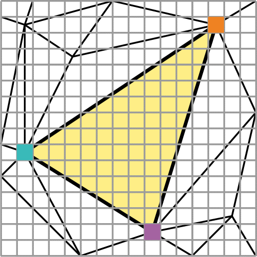
In a triangle mesh the proper pixel colors at the 3 vertices of triangle T0
have been found. Suggest an effective rendering / shading
technique to set all the other pixels covered by that
triangle.
= = = = = >
|

|
PREVIOUS
< - - - - > CS
184 HOME < - - - - > CURRENT
< - - - - > NEXT
Lecture #7 -- Wed 2/9/2011.
Continuing from last lecture ...
We are talking about the interaction between light and material surfaces.
-- Review the basic vector diagram, defining the vectors N, L, R, V.
-- Review the 4 different types of lights: ambient, directional, point-, spot- light.
-- Review: Lighting models for simple "computer-graphics
surfaces" and for real surfaces...
The two simplest, idealized surface models are:
-- the Lambert Surface that reflects light diffusely (like the
surface of chalk). When uniformly lit, its apparent brightness is
independent of viewer position;
-- the Perfect Mirror that reflects incoming light specularly in the
plane of the incident light and the surface normal, with an exit
angle on the other side of the normal vector equal to the incident angle.
Real surfaces are a mixture of both of the above types and can be represented reasonably well with the Phong model:
Highlights are modeled as "fuzzy club" shapes, in which the intensity falls of with a suitable power of the cosine of
the deviation angle from the R direction.
4. Advanced Approximations of Real Surfaces:
Real materials are more complicated:
The spreading of light (Phong
exponent) may depend on:
-- the incident angle {Torrence Sparrow model }.
-- the color of the light {spectral behavior; different
wavelenghts get absorbed / reflected differently.
-- the surface material:
==> on plastics: the
light bounces off a surface layer, and keeps most of its own color composition
(metalness factor m = 0);
==> in metal: reflected
light penetrates deeper into substrate, picks up the color of the metal ( m = 1);
==> in general: metalness
factor m varies from 0 to 1; affects the color of the highlights.
A Note on Surface Characterization:
NOTE: The notations and conventions used in different books vary.
What we use in this course is slightly richer than what Shirley
describes in [Ch 9 in 2nd Ed.] {Ch 10 in 3rd Ed.}
These are the effects that we are trying to capture in this class: Shading
Examples using spheres.
These are the main issues where physics and computer graphics differ: Relationship
between ka, kd, ks; and the c’s and the c’sBrightness Normalization.
Normally one tries to carefully choose lights so that the produced brightnesses
fall into the range: 0 to 1.0,
which is then mapped onto (say, 256) discrete beam intensities in
the CRT.
In spite of best intentions, the sum of all calculated brightnesses
may exceed unity;
this may produce strange effects if left unchecked !
--> at the very least: Clip to unity
!
--> better: Detect this, and scale down all brightness
values on the object or in the whole scene.
Now that we know what the brightness is that we would like to represent,
the question arises, how can we efficiently set all the pixels
of the right brightness ?
Rendering / Shading
For Ray-Tracing we just need to know the above surface properties, the
normal direction of the surface, and the direction to the various light
sources; then we can calculate how much light (of what color) is sent towards the eye/camera.
Superposition principle applies!
===> Assignments #4 and #5.
In the Classical Rendering Pipeline we perform the inner loop of the rendering process for the each geometrical element -- typically a triangle.
Algorithm for Polygon Rasterization (in the Classical Rendering Pipeline)
Let's assume we have done a suitable transformation to bring our
polygon into a normalized viewing volume, where we just have to do a
simple parallel projection along the z-axis (equal to setting z equal
to zero) to get the desired display of the polygon.
Now -- how do we determine in an efficient manner WHICH PIXELS should be turned on TO WHAT COLOR ?
A simple, practical paradigm: We "turn on" all the pixels that have a sampling point that
falls "inside" the polygon contour.
-- But there are some gory details!
What if the sampling point falls onto the boundary of a polygon ?
Dealing with such coincidences needs all the attention (and produces most of the bugs in your code!).
Here is a rather detailed description of a sweeping
scan-line algorithm,
raising all the issues that you would have to address when programming such an algorithm.
You don't have to program this -- but you need to understand Sections 1 and Section 5 for the exams;
in particular: Who owns the boundary pixels?
Work some examples on those raster sheets!
Sweeping Scan-line Approach -- next lecture ...
Reading Assignments:
Study: ( i.e., try to understand fully, so that you can answer
questions
on an exam):
Shirley 2nd Ed. [ 9.1-9.2;
10.1-10.8 ]. Shirley 3rd Ed. { 4.1-4.9; 10.1-10.2; 13.1-13.2 }.
Feb. 14: Take-Home Exam (open book): Due Feb.16. ==> Reserve 2-3 hrs of quiet time!
Programming Assignments:
#4: To be done individually; due (electronically submitted) before Friday 4/18, 11:00pm.
#5: To be done individually; due (electronically submitted) before Friday 4/25, 11:00pm.
PREVIOUS
< - - - - > CS
184 HOME < - - - - > CURRENT
< - - - - > NEXT
Page Editor: Carlo
H. Séquin