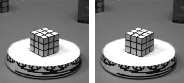
Figure 2: A Rubik's cube on a rotating turntable, taken from Russell and Norvig, ``AI, A Modern Approach'', Prentice Hall, 1995, Figure 24.8, pg. 736.
If the camera (or human eye) moves in the 3-D scene, the resulting apparent motion in the image is called the optical flow. The optical flow describes the direction and the speed of motion of the features in the image. We wil now show how to compute the optical flow from sequence of images and then derive an equations relating the 3-D structure of the world to our 2-D measurements.
An example of the optical flow pattern from the sequence of images of a rotating Rubik's cube shown in Figure 2.

Figure 2: A Rubik's cube on a rotating turntable,
taken from Russell and Norvig, ``AI, A Modern
Approach'', Prentice Hall, 1995, Figure 24.8, pg. 736.
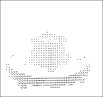
is given in Figure 3.

Figure 3: Flow vectors calculated from comparing the two images of a
Rubik's cube, taken from Russell and Norvig, ``AI, A Modern
Approach'', Prentice Hall, 1995, Figure 24.9, pg. 737.
The optical flow vector  has two components
  and
and  describing the motion of a point feature in
  and
and  direction in the image plane respectively. In order to be able to measure
optical flow we need to find corresponding points between two frames. One
possibility would be to exploit the similarity between the image patches
surrounding the individual points. There are two measures of similarity
that are commonly used for optical flow vectors. One is sum of squared
differences (SSD) between an image patch centered at a point
  , which is
a location
  at time
  and various other candidate locations
 where that patch could have moved
between two frames at time
  and
and  The goal here is to find
a displacement in the image plane
  ,
which minimizes the SSD criterion:

where the summation ranges over the image patch centered at the feature of interest. The optical flow of the chosen point feature is

. An alternative measure of similarity would be to maximize the cross-correlation between the neighboring patches in the images expressed as

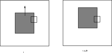
It is important to note that the optical flow is not uniquely determined by the local information. For example consider two local patches of the images observed in two consecutive times (see Figure 4).

Figure 4: In spite
of the fact that the dark square moved between the two consecutive frames,
observing purely the cut-out patch we cannot observe any change, or we may
assume that the observed pattern moved arbitrarily along the direction of
the edge.
In spite of the fact that the dark square moved between the two consecutive frames, observing purely the cut-out patch we cannot observe any change, or we may assume that the observed pattern moved arbitrarily along the direction of the edge. The fact that one cannot determine the optical flow along the direction of the brightness pattern is known as aperture problem. Have you ever thought about what might cause the barber pole illusion, where it appears that a barber shop pole is spiralling up and out. Indeed, full optical flow is best determined at the corners.