


Next: Lab 2. Magnetic Measurements
Up: No Title
Previous: Information Sheet
In RWVD, Sec. 1.13 (SES, p. 122), it is shown that Laplace's equation is satisfied for steady
current flows in a resistive medium. Thus a resistive sheet can be used as an analog to plot
the equipotentials and electric field lines, and to determine the capacitance, for a
two-dimensional electrostatic field configuration. The analog is also related to graphical
field mapping techniques as described in Sec. 1.19-1.20.
- Using an ohmeter, measure the resistance of a square (approx. 4") of resistance paper
coated with silver paint at its two opposite edges.

 . Should the measured value of
  depend on the
size of the square? Y/N.
depend on the
size of the square? Y/N. - Trace the coaxial line, template (#1) onto the center of a square (
 ") of
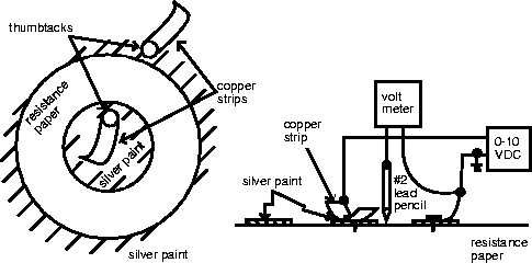
resistive paper. Carefully paint the silver around the inside of the inner circle and around
the outside of the outer circle. Use heat lamp to dry the paint.
") of
resistive paper. Carefully paint the silver around the inside of the inner circle and around
the outside of the outer circle. Use heat lamp to dry the paint. - Use thumbtacks to attach copper strips to the inner and outer electrodes. Ground the
outer electrode and apply 10 volts to the inner electrode.
- Using a digital voltmeter with lead pencil probe, find and mark the 5 volt equipotential
line. Sketch it in. Is it a circle? Y/N. Is it midway between the inner and outer
electrodes? Y/N.
- Disconnect the voltage source! Using an ohmeter, measure the resistance between the
inner and outer electrodes:
 .
. - From Eq. (2) in Sec. 1.21, the capacitance C per unit meter of the coax is given by
 . Calculate C from your measurements if
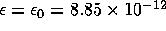 farads/meter (free space
dielectric): C= F/m. Compare with the formula in RWVD, Table 5.11b, p. 250
(SES, Exercise 4.6, p. 120):
C= F/m from table.
farads/meter (free space
dielectric): C= F/m. Compare with the formula in RWVD, Table 5.11b, p. 250
(SES, Exercise 4.6, p. 120):
C= F/m from table. - Repeat steps 2-6 for the two-wire transmission line (Template #2, trace
only the
two circles). Plot a few equipotentials (including 2.5 volts) and compare with Fig. 1.8, pp. 21
of text. Determine C from your measurements, C= F/m and compare with
C= F/m from Table 5.11b.
- Method of images, RWVD Sec. 1.18 (SES p. 124). Trace the conducting plane of template #2
between your two previously painted circles and paint the right side of the plane with silver.
Excite with 5 volts on the left circle and ground on the conducting plane, and replot the 2.5
volt equipotential. Does the method of images yield the same equipotential as found in the
two-wire line? Y/N.
- If you have time, plot a few equipotentials between the stepped conductor and the plane
conductor, template #3, and compare with Fig. 1.19c, p. 52.
Next: Lab 2. Magnetic Measurements
Up: No Title
Previous: Information Sheet
Michael Lieberman
Sat Aug 15 16:52:53 PDT 1998