In the previous lab we used the MCU to automatically measure the solar cell characteristics. In this lab we use MQTT to send the measurement results to a host (e.g. laptop) for processing and plotting.
1. Prelab
1.1. Connect to WiFi Network
Read the instructions about WiFi on the course webpage. Then write a program that connects the MCU to a WiFi access point. Test the program by verifying that it fetches a valid IP address[1]
IP address:
Add code to fetch the time from the internet. Print it out and copy it here:
Once everything is working as expected, save your program as boot.py and copy it to the MCU. The program boot.py is executed automatically every time the MCU starts (e.g. on power-up or pressing reset).
Also add the line
machine.WDT(False)to disable the “watchdog”. Watchdog’s are a feature supported by many MCUs and require a special function to be called regularly. Failure to do so results in a reboot or similar action. The purpose is to protect from programming errors which could result in an IoT device to fail in the field. We do not use this feature.
Bugs in boot.py (e.g. infinite loops) can render the MCU inaccessible or otherwise keep it from functioning correctly. Always thoroughly test code before copying it to boot.py!
|
Submit the tested boot.py with your prelab.
1.2. MQTT
Now you are ready to write the code for wireless transmission of data (e.g. solar cell characterization) from the MCU to the cloud and from there to interested clients, e.g. your laptop or a lab computer.
At the core are two programs running simultaneously on the MCU (mcu.py) and the host (host.py). The former sends measurement results to the cloud, while the latter fetches the data for plotting. Write these programs, using a public broker.
Submit mcu.py and host.py with your prelab.
1.3. Solar Powered MCU
Once the solar cell has been characterized, we can put it to use! In the next lab we will use it in a solar powered weather station. Two changes are needed:
-
Connect the solar cell output to the VUSB and GND pins respectively of the ESP32 (pin diagram). I.e. remove the potentiometer and connect the MCU in its place.
-
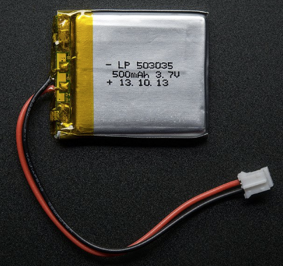
The current draw of the ESP32 is higher than the current provided by the solar cell, even in bright sun light. To address this problem, connect the LiPo battery shown in Figure 1 to the appropriate connector of the Huzzah32 board. Leave the USB connected also for a while to charge the battery. After disconnecting USB, the MCU will operate from power supplied by the battery and the solar cell. We will develop a better solution in the next lab.
In the space below, draw a modified circuit diagram showing the solar cell, INA219, and MCU connected to the solar cell for charging.
2. Lab
2.1. Characterize Solar Cell and Plot Results
Modify the code for characterizing solar cells from the previous labs to send measured data to a host using MQTT and have the host create the plot from the first lab fully automatically! I.e. plot voltage, current and power versus resistance on a logarithmic scale.
Annotate the plot by printing out the maximum power, as well as the corresponding voltage, current and resistance[2].
You will need some mechanism for the host to know when to start plotting. For example, you could check that the measured resistance covers an appropriate range, e.g. 5Ω to 1kΩ.
Demonstrate your setup and show the plot with annotations to the GSI.
2.2. Autonomous Operation
Modify your circuit so that the solar cell charges the LiPo battery connected to the Huzzah32 board (instead of the potentiometer). Start a program that blinks the on-board LED and disconnect the USB cable. The MCU is now powered from the LiPo battery and solar cell.
Show the blinking LED to the GSI.