1. Overview
Microcontrollers (MCUs) are full-fledged computers targeted for “embedded” applications. Unlike desktops or smartphones which distribute functions over several chips, microcontrollers typically are self-contained, meaning that the computing engine, memory, and interfaces reside on a single chip (Figure 1). Consequently they are small (down to the size of a peppercorn), inexpensive, and dissipate little power. They include a flexible interface to attach a wide variety of peripherals such sensors, LEDs, motor controllers etc. Many are available with on-chip wireless communication interfaces.

Table 1 shows the specifications of typical microcontrollers used for IoT applications. The specifications of a Raspberry Pi, a low-end desktop computer, are included for comparison. Program execution speed is roughly proportional to clock rate: higher is faster, but also means more power dissipation. Random access memory (RAM) is volatile, i.e. looses contents when power is removed. It is used to store variables and datastructures. The Raspberry Pi’s RAM is much larger but off-chip, increasing size and cost. Flash memory is non-volatile and therefore a good choice for storing programs, measurement results, and other permanent data. Off-chip flash like that of the ESP32 is often larger than on-chip memory, but again adds to size and cost, and, more importantly, often suffers from slower access speed, compromising program execution.
Many IoT microcontrollers feature on-chip radios for standards such as WiFi and Bluetooth. The Raspberry Pi relies on off-chip circuits to provide this functionality.
| Specification | ESP32 | nRF52832 | Raspberry Pi 3B |
|---|---|---|---|
Clock rate |
240 MHz |
64 MHz |
1.2 GHz |
RAM |
520 kB |
64 kB |
(1 GB) |
Flash |
(4MB) |
512 kB |
n/a |
Wireless |
Wifi, Bluetooth |
Bluetooth |
(Wifi, Bluetooth) |
Since microcontrollers are usually dedicated to a single task such as collecting data from sensors or controlling the motors of a robot, they typically have no or only a very simple operating system. This enables microcontrollers to react very rapidly to external events.
Invented in 1971, microcontrollers are still undergoing rapid development, with features and capabilities continually being added. At any time hundreds of options are available to meet a wide range of requirements for performance, memory, peripherals, energy efficiency and cost.
2. Pin Diagram
Figure 2 shows the connection diagram of the Huzzah32 microcontroller board, an ESP32 microcontroller mounted on a printed circuit board (PCB) with some additional components to support rapid prototyping.
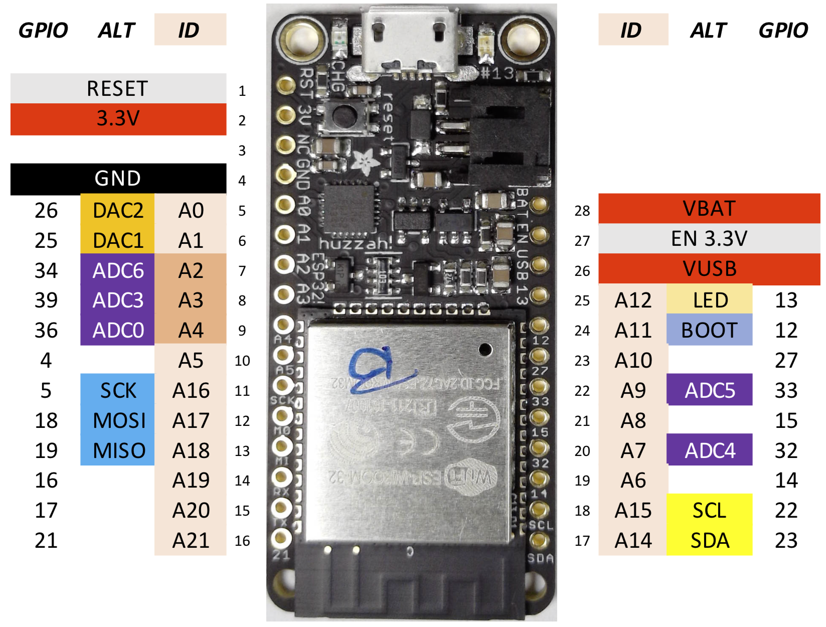
The board features a USB connector for programming, a connector for an optional lithium backup battery enabling autonomous operation, and an array of “pins” (electrical connections) on either side of the board.
Several pins are dedicated to chip power:
| Name | Function |
|---|---|
|
3.3V output from the on-board regulator. Can supply up to 500mA. |
|
Common ground for power and logic. |
|
Positive voltage from USB jack, if connected. ~5V. |
|
Positive voltage from the backup Lipoly battery, if connected. ~3.7V. |
|
3.3V regulator enable pin. Tie to ground to disable. |
|
Reset, tie to |
The remaining pins are used for general purpose input & output (GPIO).
3. Programming
3.1. Language
Natively computers “speak” machine language, also called assembly language. Since assembly is very low level and time consuming to work with, most actual programming is done in a higher level language.
Presently, C is most widely used for microcontroller programming. More recently, languages such as Python and Javascript have appeared as alternatives. Compared to C, these newer languages offer higher productivity at the expense of slower execution speed and requiring more memory. Given the ever increasing performance of computers the tradeoff can be attractive.
Here we use a derivative of Python called MicroPython that has been optimized to run on resource constrained microcontrollers with limited memory. The language implements the Python 3.4 syntax with extensions for asynchronous programming introduced in Python 3.5.
3.2. Running Programs
Since microcontrollers lack a keyboard and display they rely on a host computer, such as a laptop, for uploading and running programs.
The process uses programs that are invoked from the command-line, a textual interface, on the host computer you are using. Instructions for getting a command prompt can be found on the web, e.g. for Windows or Mac.
You can either use a custom program, shell49, or a terminal program to interact with the MCU. shell49 has more features but unfortunately does not run correctly on all computers. Especially Windows appears to have problems. In this case (or based on preference), use the second option.
3.2.1. Shell49
shell49 is a program running on a host computer (e.g. laptop) that connects to the ESP32 via USB (or WiFi) to interact with the MicroPython interpreter on the ESP32.
To set up MicroPython on the Huzzah32 board, remove the Huzzah32 board from its packaging. Be careful not to touch any conductive surfaces (e.g.\ metals) with the Huzzah32 boards when powered to prevent electrical damage to the board. The headers have been pre-soldered for you, protect your board by inserting into a breadboard and connect it to the host computer using a micro-USB cable. After the board receives power through the USB connection, a yellow LED will start flashing rapidly. This is normal.
Follow the instructions at https://github.com/bboser/IoT49/blob/master/doc/install.md to flash the MicroPython firmware to the Huzzah32. You can do this either on the lab computer or on your own hardware.
3.2.2. Terminal Program
Windows is finicky. You might not able to follow the instructions at https://github.com/bboser/IoT49/blob/master/doc/install.md all the way through. You should be able to flash the firmware from shell49, but once you get to the point where you are trying to write
connect serial
repl
you may see an error to the effect that your system is timing out without connecting. If that happens to you, there is a workaround!
To begin, we’re going to go to the git repo https://github.com/chrisb2/pyb_ina219. Hit the ‘clone or download’ button, choose the .zip file option, and extract it to somewhere on your computer. Use the ‘cd’ terminal command to move into the newly-created ‘pyb_ina219-master’ folder.
Install `ampy`[1] by typing
pip install adafruit-ampyat the command prompt. Then use ampy to copy the ina219.py file on the ESP32 with the command[2]
ampy --port COM4 put ina219.pyNow you are going to need to open a channel for serial communication to your ESP board. Windows has a few options for doing that; we are going to choose Tera Term. Download and run the .exe file listed here to install: https://osdn.net/projects/ttssh2/releases/70355.
After Tera Term has been installed, run it (make sure your ESP32 has been plugged in, and that your command prompt is closed- you can’t have two different terminal windows communicating with your board at the same time). Select ‘serial’ from the connection options and choose the right port number. This will open a terminal that may immediately start spewing strange symbols at you. This is because it is reading information from your MCU at a different speed than your MCU is writing. To fix that, go to setup>serial port and set the speed to 115200. Hitting ‘enter’ should then give you a MicroPython command prompt.
From that prompt, you should be able to directly execute the code you’ll need for the solar cell characterization lab! Try entering the code from the INA219 course slides (slide #24) to verify that it works.