CS 184: COMPUTER GRAPHICS
PREVIOUS
< - - - - > CS
184 HOME < - - - - > CURRENT
< - - - - > NEXT
Lecture #19 -- Mon 4/4/2011.
Warm-up Problem:
How many "Degrees of Freedom" (DoF) are there for:
1.) all cubic Bezier curves in the plane ?
2.) all circular disks in 3D space ?
3.) all infinitely long straight lines in 3D space ?
4.) the mechanical (2D) linkage shown at right ?
|

|
Some Very Special As#8 Submissions:
Vinod-Chandru
Brandon-Wang
Sangha-Im
Kevin-Lee
Whitney-Lai
The Classical Rendering Pipeline
For comparison: The 3 basic rendering models.
The
main transformation steps of the Classical Rendering Pipeline.
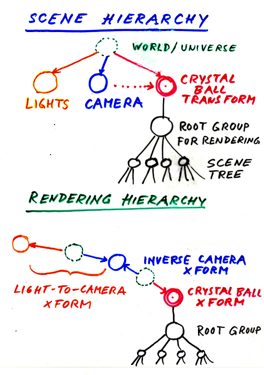
Scene Hierarchy --> Rendering Hierarchy
Put the Camera node "above" the World node.
Use inverse transformations whenever you need to move "upwards" in
the scene tree.
Finding the proper sequence ...
We need to think about the exact order in which we want to do all the
necessary operations:
-- culling, backface elimination, clipping, shading, rasterizing ...
General principles:
-- Do least expensive, most work-saving steps first.
-- Don't throw away information you may need later.
-
Read in the scene description (build appropriate internal data structures).
-
Process the master geometry at the leaf nodes (calculate face and/or
vertex normals).
-
Define a camera type (parallel or perspective projection; viewing angle / zoom).
-
Place this camera in the World (most conveniently using the "look_at" transformation; this defines VRCS = View Reference Coordinate System).
-
Find how the World lies in the VRCS coordinate system (use inverse
camera transformation).
-
Fit the view volume into the canonical half-cube (non-uniform scaling, possibly perspective transformation).
-
Do hierarchical bounding-box culling in 3D (using 6-bit outcodes
on the 8 Bbox corners).
-
Eliminate the backwards facing polygons (check z-component of transformed
normal on best-fitting plane).
-
Clip the polygons at the leaves of the scene hierarchy that straddle
the canonical half-cube (against 6 planes).
-
Compute the color/shading on the surviving polygon fragments (using proper lighting model in 3D).
-
Raster-fill the polygons (turn on the pixels that represent the
visible area of the polygon).
-
Resolve overlapping polygons (use Z-buffer to render front-most
pixel).
(Extra steps may be introduces when using GPU + Shader languages).
Some issues that need special consideration:
Viewing / Rendering
Rendering means to take a snapshot of a part of the World from the
location of the eye or the camera.
I.e., we ask the question: "What does the world look like from the point
of view of the camera?"
The key parameters of camera placement are its position (3 DOF) and
orientation
(3 DOF);
( These are the 6 DOF of a rigid body in 3D ).
This can be conveniently specified with a Look_at Transformation:
-- the position/origin of the new system (eye),
-- a view reference point that will lie on the -n-axis (vrp)
-- and an up vector that should project onto the v-axis in the
uv-plane (up).
All this defines
the View Reference Coordinate System (VRCS):
The VRCS has its origin at the camera lens,
its n-axis pointing through the lens straight into the camera,
its v-axis pointing (typically) upwards,
and its u-axis at right angle to both other axes,
so as to form a right-handed coordinate system.
For the rendering process, we transform the parts of the world to be rendered into this new reference
frame, and then project onto the image plane.
The desired transformation into the VRCS can most easily be computed by modifying
the scene hierarchy so that the camera becomes its "root."
We then calculate
the way the World lies in the camera system by inverting the compound matrix
string that leads from the world to the camera.
Every instanced polygon
in the scene can be described in the framework of the camera with a single compound
matrix,
and we can easily determine whether it can be seen and how it would
appear to the camera.
A technique similar to this Reverse Camera Path will be used when we will have to deal with the
individual illuminations produced by one or more light sources:
We will
make each one in turn temporarily the root of the hierarchy and determine
how each polygon appears in that special reference coordinate system for
a particular light, so that we can determine how much light from that source
ends up on each polygon (and what might be shadowed).
Projections (~ "batch processing" of all the operations that were done with individual rays in ray casting).
In the simplest case we may use a Parallel-Projection Camera
In this case our 3D to 2D transformation is simply to ignore the
z-coordinate values, once we have found the properly oriented VRCS.
But more often we will use a Perspective Projection
In this case, additional parameters to describe the camera are needed
"Focal length" --> determines the opening angle of viewing pyramid;
"Film or light sensor geometry" --> positioning and size of the imaging plane and the window
of interest; also front and back clipping planes.
These camera parameters can be described with 6 numbers -- specifying a 3D "world window box" (left, right, bottom, top, far, near )
-- a rectangle in the plane
z = -1, and 2 z-values for clipping planes (these will get normalized to the back and front faces of the canonical half-cube).
This leads to the
There are many different camera types and projection situations ...
How do you conveniently and unambiguously specify all required camera/viewing
parameters ?
- Position and orient the camera with the "look_at" transformation. (This defines the geometry of the VRCS completely).
- The z-axis (n-axis) is the view plane normal.
- A rectangle in the viewing plane (z = -1) specifies the size of the film (and thus the lateral dimensions of the viewing
volume).
- If the center of that rectangle lies on the -z-axis (-n-axis), we get a
symmetrical view volume (else we get a somewhat slanted view).
- A slanted view in parallel projection allows us to do oblique projections.
This will require a shear transformation to get
such a view volume into the canonical viewing box. - Two z-values specify back and front cutoff planes and thereby define a finite 3D volume of interest.
These will get normalized to the back and front faces of the canonical brick-like viewing box.
How does the final image change, as we change some of the parameters of the perspective projection ?
In the perspective case, the size of the image depends on the
distance
between camera and original.
The key feature is that geometry further away gets reduced by the factor 1/distance.
Rather than doing a real projection -- and thereby loosing the depth (ordering)
information,
we perform a 3D
to 3D transformation
of the piece of the World that we are interested in
into a canonical view volume where it is easy to do culling
and clipping.
1.) First we perform a shear operation (if necessary) to bring the center
of the window n the n=-1 plane
(which specifies the opening of the view frustum)
onto the n-axis.
2.) Then we perform a non-uniform scaling in all three axes so that the
half-angles of the view frustum
in the x- and y-directions are set at 45 degrees, and so that the back
clipping plane is brought to n=-1.
3.) This is all very similar to the case of parallel projection; but now
comes the really nifty step:
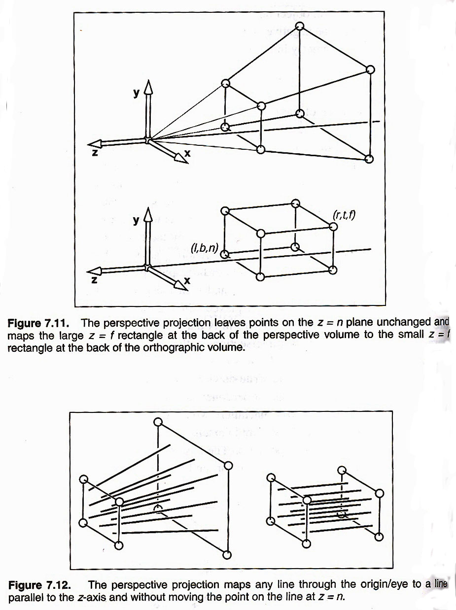
The
Perspective Transformation:
This is a clever 3D to 3D transformation (using homogeneous coordinates)
that distorts the u and v dimensions in just the right way,
so as to achieve
a proper perspective look, when we finally perform a parallel projection along the n-axis.
It also maintains all relative orderings in the n-direction, so that
we can do hidden surface elimination later.
Furthermore, it keeps the back clipping plane (B) at the n=-1 plane,
and it moves the front clipping plane (F) to the n=0 plane.
[ Shirley takes an intermediate step and keeps (B) and (F) in the same place; this yields a simpler "perspective matrix" Mp ]
Now we have the whole view volume mapped into the same canonical half-brick as in the case of a parallel projection.
In general, it maps the point {x, y, z, 1} into {x, y, (z - zmin)/(1
+ zmin), -z}
.
It also maps the eye to infinity.
Furthermore, rays through the eye become parallel; and parallel lines converge in a point called the Vanishing Point.
Finally: The Actual Projection to 2D:
Once we have everything of interest within the canonical half-cube, doing the projection to 2D is trivial:
Just set the z-coordinate to zero !
Reading Assignments:
Shirley: [ 2nd Ed: Ch.7, Ch.12 ]
Shirley: { 3rd Ed: Ch.7, Ch.8 }
Programming Assignment #9:
May be done in pairs; due (electronically submitted) before Friday April 8, 11:00pm
PREVIOUS
< - - - - > CS
184 HOME < - - - - > CURRENT
< - - - - > NEXT
Page Editor: Carlo
H. Séquin