Geometry Nodes
The geometry nodes are the leaf nodes of the scene hiearchy which
actually contain geometry. The basic object, as defined by the object statement, is a collection of polygons.
The other primitive objects defined in SLIDE are the
parameterized surfaces:
sphere,
cylinder,
cone,
torus,
cyclide,
bsplinecurve,
bezeircurve,
polyline,
sweep,
bsplinepatch, and
bezeirpatch.
The object differs from these other surface primitives because
it is not defined over a rectangular domain in texture space. The
object does not have a field for adjusting this texture
parameterization, and instead the texture coordinates for the faces
which comprise an object are defined within the point entity.
All geometric nodes may have these fields:
| SLIDE Definition |
tclinit Definition |
|
|
| SLIDE Defaults |
tclinit Defaults |
| primitive_object id
|
| |
texture ( 0.0 0.0 ) [( 1.0 0.0 )] ( 1.0 1.0 ) [( 0.0 1.0 )]
solid SLF_SOLID
surface SLF_INHERIT
shading SLF_INHERIT
lod SLF_FULL
ribbegin SLF_NULL
ribend SLF_NULL
|
| endprimitive_object |
|
| slide create primitive_object id \
|
| |
-texture { 0.0 0.0 } [{ 1.0 0.0 }] { 1.0 1.0 } [{ 0.0 1.0 }] \
-solid $SLF_SOLID \
-surface $SLF_INHERIT \
-shading $SLF_INHERIT \
-lod $SLF_FULL \
-ribbegin $SLF_NULL \
-ribend $SLF_NULL
|
|
| Field |
Description |
| texture |
|
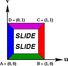
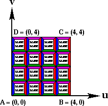
Two or four (u, v, w) triples of texture coordinates,
A, C or A, B, C, D respectively. These values are in
texture space and define how to map the texture onto the geometry of
the surface. A, B, C, D run around the contour of the surface
patch in counterclockwise order. If only A, C are specified
then B = (Cu, Av)
and D = (Au, Bv).
This type of modification to the texture parameterization is
convenient for tiling a texture over a surface.
| Complete Texture on a Square |
Texture Tiled 4X on a Square |
 |
 |
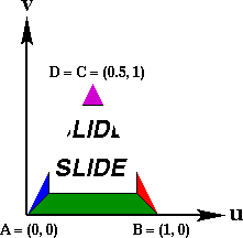
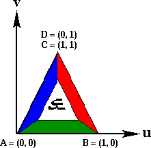
The four texture coordinate points A, B, C, D can be used
to do the same tiling operation in a less convenient way or to crop
nonrectangular quadrilaterals out of the texture image. An example of
this would be clipping out a triangular region from a texture image to
map on a degenerate surface patch. If the complete texture image is
used on a degenerate quadrilateral patch then the texture will take on
unpredictable warping behaviors.
Triangular Texture Region
on Degenerate Quadrilateral |
Complete Texture
on Degenerate Quadrilateral |
 |
 |
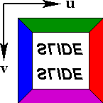
The abstraction described above assumes a rectangular texture
domain with a right handed coordinate system. The reality is that
most bitmap image formats, including GIF, are defined with a left
handed coordinate system, the y-axis pointing down. To make
the abstraction valid, it is useful to store texture map images
mirrored in the y-direction.
| Texture Domain Abstraction |
Reality of GIF and
other Image Formats |
 |
 |
NOTE: This field does not apply for object.
|
|
| solid |
See the Solid Type |
| shading |
See the Shading Type |
| lod |
See the LOD Type |
Example: primitives.slf
The SLIDE file primitives.slf
is an interactive demo of all of the SLIDE geometric primitive nodes.
This file allows the viewer to select a primitive to work with. When
a new primitive is selected GUI for that type of primitive appears, so
that the viewer can interactive adjust parameters of the primitive to
better understand what the parameters control. Many of the images in
the following section were created using this example.
object
The object statement is used to create general polyhedrons.
An object is really just a group of faces. This group of faces needs
not enclose a volume or even be connected. The faces are specified in
the face_idlist.
| SLIDE Definition |
tclinit Definition |
|
|
| SLIDE Defaults |
tclinit Defaults |
| object id ( face_idlist )
|
| |
solid SLF_SOLID
surface SLF_INHERIT
shading SLF_INHERIT
lod SLF_FULL
ribbegin SLF_NULL
ribend SLF_NULL
|
| endobject |
|
| slide create object
id { face_idlist } \
|
| |
-solid $SLF_SOLID \
-surface $SLF_INHERIT \
-shading $SLF_INHERIT \
-lod $SLF_FULL \
-ribbegin $SLF_NULL \
-ribend $SLF_NULL
|
|
Example: Tetrahedron, a Simple Polyhedron
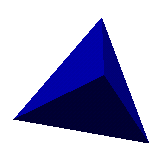 |
The file tetrahedron.slf defines a
regular tetrahedron centered at the origin which has been given the
identifier oTetra. The object is a solid and should be
rendered with flat shading to maintain the sharp edges of the
tetrahedron. No surface is currently associated with the faces,
indicating that the surface properties can be specified later during
instancing. |
| Static SLIDE |
Procedural SLIDE |
# Tetrahedron

point p1 ( 1 -1  1) endpoint
point p2 (-1  1  1) endpoint
point p3 ( 1  1 -1) endpoint
point p4 (-1 -1 -1) endpoint

face f1 (p2 p1 p3) endface
face f2 (p4 p3 p1) endface
face f3 (p3 p4 p2) endface
face f4 (p1 p2 p4) endface

object oTetra (f1 f2 f3 f4)
  solid SLF_SOLID
  shading SLF_FLAT
endobject
|
# Tetrahedron
tclinit {
  slide create point p1 {  1 -1  1 }
  slide create point p2 { -1  1  1 }
  slide create point p3 {  1  1 -1 }
  slide create point p4 { -1 -1 -1 }

  slide create face f1 { p2 p1 p3 }
  slide create face f2 { p4 p3 p1 }
  slide create face f3 { p3 p4 p2 }
  slide create face f4 { p1 p2 p4 }

  slide create object oTetra { f1 f2 f3 f4 } \
    -solid $SLF_SOLID \
    -shading $SLF_FLAT
}
|
Normals
Normals are attached to faces and points. Normals are utilized
for a number of different operations. Face normals are used in the
visibility test used to cull away back facing polygons which are part
of solid objects. Face and point normals are used in lighting
computations. The face normal is used for flat shaded polygons, while
the point normals are used for Gouraud shaded polygons.
Face normals are calculated based on the orientation defined by
the order in which its vertices are specified around its contour and
the right-hand rule for cross products. For a more detailed
explanation of the computation involved see the backface
culling page.
|
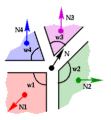
Point normals are assigned one of two different ways. Point
normals can be specified in the point statement, in which case this
normal is used for this point no matter how many faces reference it.
If no normal is explicitly defined for a point then a normal is
automatically calculated for the point using a weighted average of
face normals of all the faces which reference that point. The face
normals are weighted by the magnitude of the angle enclosed by the
edges of the face which are adjacent to the point within the plane of
the face:
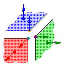
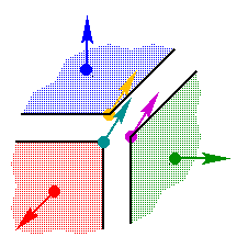
The example to the right shows a shared vertex at the corner of a
cube where one of the square faces is represented by two coplanar
triangles. Because of the weighted average of the face normals the
resulting point normal N lies along the space diagonal of the
cube. If an unweighted average of the face normals had been employed,
N would swing more vertical because it has two normal vectors
contributing in that direction.
|
|
Example: Normals
The manner in which points are shared between faces can lead to
some unexpected lighting phenomena. The example file normals.slf contains three
different representations of a cube: a cube with shared vertices and
no point normals, a cube without shared vertices and no point normals,
and a cube without shared vertices and point normals assigned to make
it act like the first cube. Each representation invokes a different
method for calculating the point normals for the corners of the cube.
The example also shows the results of these differences with different
shading and light situations, i.e. flat vs. Gouraud shading.
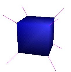
1. Cube with Shared Vertices
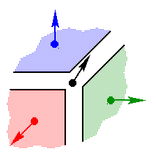
The first cube is constructed with 8 points for the corners and 6
square faces for the sides. Each one of these points is referenced or
shared by three faces. The point normals have not been specified, so
they will be calculated automatically using the rules from above. The
resulting point normal vectors lie along the space diagonals of the
cube. This would be a desireable geometry for approximating the
shading behavior of a sphere using the very rough polygonal model of a
cube.
##################################################
# Cube with shared vertices
#
|
point pXYZ (  1  1  1 ) endpoint
point pxYZ ( -1  1  1 ) endpoint
point pXyZ (  1 -1  1 ) endpoint
point pxyZ ( -1 -1  1 ) endpoint
point pXYz (  1  1 -1 ) endpoint
point pxYz ( -1  1 -1 ) endpoint
point pXyz (  1 -1 -1 ) endpoint
point pxyz ( -1 -1 -1 ) endpoint

face fX ( pXYZ pXyZ pXyz pXYz )
endface
face fx ( pxYZ pxYz pxyz pxyZ )
endface
face fY ( pXYZ pXYz pxYz pxYZ )
endface
face fy ( pXyZ pxyZ pxyz pXyz )
endface
face fZ ( pXYZ pxYZ pxyZ pXyZ )
endface
face fz ( pXYz pXyz pxyz pxYz )
endface

object oCubeShared ( fX fx fY fy fZ fz )
endobject
|
| Corner Zoom |
 |
|
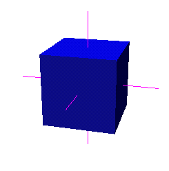
This description of a cube is good because it is very compact, but
it has shading behavior which may not be desireable. When the cube is
lit with flat shading it looks like a cube. This will be true in all
three examples because the face normals are used for lighting with
flat shading. The Gouraud shaded version on the other hand appears
strange when lit. The discontinuities at the edges of the cube are
washed away. This is due to the fact that each SLIDE point can only
have one normal attached to it, so at one corner of the cube each face
is getting the same color calculated. This is desireable behavior for
approximating a smooth surface with a polyhedron.
| Flat Shading |
Gouraud Shading |
 |
 |
2. Cube with Unshared Vertices
The second cube is constructed such that each of the 6 faces have 4
points of their own. The point normals have not been defined, so they
will be automatically calculated using the face normals which
reference the point. Each point is only referenced by a single point,
so each point will simply get the appropriate face normal. This means
that each corner will have three separate points which each have
different normals.
The geometry as described above could be defined by tediously
creating 24 points and 6 faces which reference it, but instead in the
description below a single face is defined in an object and then that
face is instanced 6 times in a group to create the cube.
##################################################
# Cube with unshared vertices
#

point pSquareXY (  1  1  1 ) endpoint
point pSquarexY ( -1  1  1 ) endpoint
point pSquareXy (  1 -1  1 ) endpoint
point pSquarexy ( -1 -1  1 ) endpoint

face fSquare ( pSquareXY pSquarexY pSquarexy pSquareXy )
endface
|
object oSquare ( fSquare )
endobject

group gCubeUnshared
  # Equivalent to fX
  instance oSquare
    rotate ( 0 1 0 ) ( 90 )
  endinstance
  # Equivalent to fx
  instance oSquare
    rotate ( 0 1 0 ) ( -90 )
  endinstance
  # Equivalent to fY
  instance oSquare
    rotate ( 1 0 0 ) ( -90 )
  endinstance
  # Equivalent to fy
  instance oSquare
    rotate ( 1 0 0 ) ( 90 )
  endinstance
  # Equivalent to fZ
  instance oSquare
  endinstance
  # Equivalent to fz
  instance oSquare
    rotate ( 0 1 0 ) ( 180 )
  endinstance
endgroup
|
| Corner Zoom |
 |
|
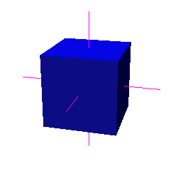
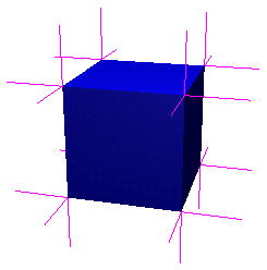
This cube behaves differently than the first when lit. Flat
shading produces the same image as the previous example, but Gouraud
shading has a very different result. There are now three points at
each corner of the cube, each with a different normal. This will
produce a discontinuity in lighting at the corner which will also be
appearant along the edges of the cube with Gouraud color
interpolation. This model is not good for approximating a smooth
surface, but it is a better model than simple flat shading for
representing a faceted object. Flat shading only calculates a single
color value for a face and then applies it over the entire face. Flat
shading is not able to represent the gradation of color which is
normally seen on a lit surface. The cube with unshared vertices and
Gouraud shading makes a better approximation to how a lit cube would
look. Four color values are computed for and then smoothly
interpolated across each face. Even better representations of the
lighting of a cube can be made by subdividing the faces of the cube
into even smaller polygons. This subdivision is needed more when
specular surface properties are used.
| Flat Shading |
Gouraud Shading |
 |
 |
3. Cube with Unshared Vertices and Assigned Point Normals
The third cube is defined the same way as the second with unshared
vertices, but the point normals have been defined in this example so
that it will behave like the first cube with shared vertices when lit.
The point of this example is to show the power of user assigned point
normals.
##################################################
# Cube with unshared vertices and point normals
#

point pNormalsXY ( 1  1  1)
  normal ( 1  1  1)
endpoint
point pNormalsxY (-1  1  1)
  normal (-1  1  1)
endpoint
point pNormalsXy ( 1 -1  1)
  normal ( 1 -1  1)
endpoint
point pNormalsxy (-1 -1  1)
  normal (-1 -1  1)
endpoint

face fNormals ( pNormalsXY pNormalsxY pNormalsxy pNormalsXy )
endface
|
object oNormals ( fNormals )
endobject

group gCubeNormals
  # Equivalent to fX
  instance oNormals
    rotate ( 0 1 0 ) ( 90 )
  endinstance
  # Equivalent to fx
  instance oNormals
    rotate ( 0 1 0 ) ( -90 )
  endinstance
  # Equivalent to fY
  instance oNormals
    rotate ( 1 0 0 ) ( -90 )
  endinstance
  # Equivalent to fy
  instance oNormals
    rotate ( 1 0 0 ) ( 90 )
  endinstance
  # Equivalent to fZ
  instance oNormals
  endinstance
  # Equivalent to fz
  instance oNormals
    rotate ( 0 1 0 ) ( 180 )
  endinstance
endgroup
|
| Corner Zoom |
 |
|
Each corner of this cube has 3 separate points, but all of the
normals of these points have been assigned to be the vector along the
space diagonal of the cube. The resulting images under lighting look
exactly the same as the cube with shared vertices.
| Flat Shading |
Gouraud Shading |
 |
 |
sphere
A sphere statement describes a portion of a spherical shell
that is parameteratized based on latitude and longitude. The
z-axis is the axis for the poles of the sphere.
| SLIDE Definition |
tclinit Definition |
| sphere id
|
| |
radius radius_float
zmin zmin_float
zmax zmax_float
thetamax thetamax_float
zslices zslices_int
thetaslices thetaslices_int
texture ( texture_triple ) [( texture_triple )] ( texture_triple ) [( texture_triple )]
solid solid_flag
surface surface_id
shading shading_flag
lod lod_flag
ribbegin "rib_string"
ribend "rib_string"
|
| endsphere |
|
| slide create sphere id \
|
| |
-radius radius_float \
-zmin zmin_float \
-zmax zmax_float \
-thetamax thetamax_float \
-zslices zslices_int \
-thetaslices thetaslices_int \
-texture { texture_triple } [{ texture_triple }] { texture_triple } [{ texture_triple }] \
-solid solid_flag \
-surface surface_id \
-shading shading_flag \
-lod lod_flag \
-ribbegin "rib_string" \
-ribend "rib_string" \
|
|
| SLIDE Defaults |
tclinit Defaults |
| sphere id
|
| |
radius 1.0
zmin 0.0
zmax 1.0
thetamax 360.0
zslices 8
thetaslices 8
texture ( 0.0 0.0 ) [( 1.0 0.0 )] ( 1.0 1.0 ) [( 0.0 1.0 )]
solid SLF_SOLID
surface SLF_INHERIT
shading SLF_INHERIT
lod SLF_FULL
ribbegin SLF_NULL
ribend SLF_NULL
|
| endsphere |
|
| slide create sphere id \
|
| |
-radius 1.0 \
-zmin 0.0 \
-zmax 1.0 \
-thetamax 360.0 \
-zslices 8 \
-thetaslices 8 \
-texture { 0.0 0.0 } [{ 1.0 0.0 }] { 1.0 1.0 } [{ 0.0 1.0 }] \
-solid $SLF_SOLID \
-surface $SLF_INHERIT \
-shading $SLF_INHERIT \
-lod $SLF_FULL \
-ribbegin $SLF_NULL \
-ribend $SLF_NULL
|
|
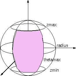
| Field |
Description |
| radius |
The radius of the sphere
0.0 < radius
|
| zmin |
The minimum z value is expressed as a percentage of the diameter.
This defines the minimum latitude line of the patch on the sphere.
The surface is bounded by the plane parallel to the xy-plane at
this z height. zmin can be greater than zmax in which
case the surface will be turned inside out.
0.0 <= zmin <= 1.0
|
| zmax |
The maximum z value is expressed as a percentage of the diameter.
This defines the maximum latitude line of the patch on the sphere.
The surface is bounded by the plane parallel to the xy-plane at
this z height. zmax can be less than zmax in which
case the surface will be turned inside out.
0.0 <= zmax <= 1.0
|
| thetamax |
thetamax is specified in degrees. The surface begins
at the x-axis and circles the z-axis by the angle
theta until thetamax is reached.
|
| zslices |
The integer number of latitudinal triangle strips used to
tesselate the sphere patch. The strips are separated evenly in
angle.
0 < zslices
|
| thetaslices |
The integer number of longitudinal triangle strips used to
tesselate the sphere patch. The strips are separated evenly in
angle.
0 < thetaslices
|
Example: Sphere Patch
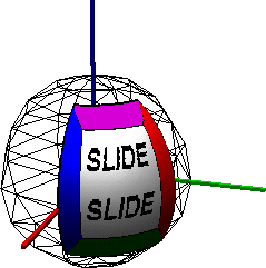
This sphere patch was made using the primitives.slf example. The parameters
below define the texture mapped patch, and the wire frame sphere
illustrates the default parameter settings.
| Static SLIDE |
Procedural SLIDE |
# Sphere Patch

sphere sph
  surface sTile
  solid SLF_HOLLOW
  shading SLF_GOURAUD
  radius 1.0
  zmin 0.25
  zmax 0.925
  thetamax 67.0
  texture ( 0 0 ) ( 1 1 )
endsphere
|
# Sphere Patch
tclinit {
  slide create sphere sph \
    -surface sTile \
    -solid SLF_HOLLOW \
    -shading SLF_GOURAUD \
    -radius 1.0 \
    -zmin 0.25 \
    -zmax 0.925 \
    -thetamax 67.0 \
    -texture { 0 0 } { 1 1 }
}
|
cylinder
A cylinder statement describes a portion of a cylindrical
shell whose central axis is the z-axis.
| SLIDE Definition |
tclinit Definition |
| cylinder id
|
| |
radius radius_float
zmin zmin_float
zmax zmax_float
thetamax thetamax_float
zslices zslices_int
thetaslices thetaslices_int
begincap begincap_bool
endcap endcap_bool
texture ( texture_triple ) [( texture_triple )] ( texture_triple ) [( texture_triple )]
solid solid_flag
surface surface_id
shading shading_flag
lod lod_flag
ribbegin "rib_string"
ribend "rib_string"
|
| endcylinder |
|
slide create cylinderid \
|
|
| |
-radius radius_float \
-zmin zmin_float \
-zmax zmax_float \
-thetamax thetamax_float \
-zslices zslices_int \
-thetaslices thetaslices_int \
-begincap begincap_bool
-endcap endcap_bool
-texture { texture_triple } [{ texture_triple }] { texture_triple } [{ texture_triple }] \
-solid solid_flag \
-surface surface_id \
-shading shading_flag \
-lod lod_flag \
-ribbegin "rib_string" \
-ribend "rib_string" \
|
|
| SLIDE Defaults |
tclinit Defaults |
| cylinder id
|
| |
radius 1.0
zmin 0.0
zmax 1.0
thetamax 360.0
zslices 1
thetaslices 8
begincap 0
endcap 0
texture ( 0.0 0.0 ) [( 1.0 0.0 )] ( 1.0 1.0 ) [( 0.0 1.0 )]
solid SLF_SOLID
surface SLF_INHERIT
shading SLF_INHERIT
lod SLF_FULL
ribbegin SLF_NULL
ribend SLF_NULL
|
| endcylinder |
|
| slide create cylinder id \
|
| |
-radius 1.0 \
-zmin 0.0 \
-zmax 1.0 \
-thetamax 360.0 \
-zslices 1 \
-thetaslices 8 \
-begincap 0
-endcap 0
-texture { 0.0 0.0 } [{ 1.0 0.0 }] { 1.0 1.0 } [{ 0.0 1.0 }] \
-solid $SLF_SOLID \
-surface $SLF_INHERIT \
-shading $SLF_INHERIT \
-lod $SLF_FULL \
-ribbegin $SLF_NULL \
-ribend $SLF_NULL
|
|
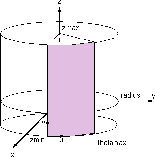
| Field |
Description |
| radius |
The radius of the circular cross section of the cylinder in
the xy-plane.
0.0 < radius
|
| zmin |
The minimum z value, this defines the minimum latitude
line of the patch on the cylinder. The surface is bounded by the plane
parallel to the xy-plane at this z height. zmin
can be greater than zmax in which case the surface will be
turned inside out.
|
| zmax |
The maximum z value, this defines the maximum latitude line
of the patch on the cylinder. The surface is bounded by the plane
parallel to the xy-plane at this z height. zmax
can be less than zmax in which case the surface will be turned
inside out.
|
| thetamax |
thetamax is specified in degrees. The surface begins
at the x-axis and circles the z-axis by the angle
theta until thetamax is reached.
|
| zslices |
The integer number of triangle strips parallel to the
xy-plane that are used to tesselate the cylinder patch. The
strips are separated evenly in z height.
0 < zslices
|
| thetaslices |
The integer number of triangle strips parallel to the
z-axis that are used to tesselate the cylinder patch. The
strips are separated evenly in angle.
0 < thetaslices
|
| begincap |
Boolean that specifies whether or not to draw a cap at the zmin.
|
| endcap |
Boolean that specifies whether or not to draw a cap at the zmax.
|
Example: Cylinder Patch
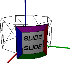
This cylinder patch was made using the primitives.slf example. The parameters
below define the texture mapped patch, and the wire frame cylinder
illustrates the default parameter settings.
| Static SLIDE |
Procedural SLIDE |
# Cylinder Patch

cylinder cyl
  surface sTile
  solid SLF_HOLLOW
  shading SLF_GOURAUD
  radius 1.0
  zmin -0.2
  zmax 0.9
  thetamax 67.0
  texture ( 0 0 ) ( 1 1 )
endcylinder
|
# Cylinder Patch
tclinit {
  slide create cylinder cyl \
    -surface sTile \
    -solid SLF_HOLLOW \
    -shading SLF_GOURAUD \
    -radius 1.0 \
    -zmin -0.2 \
    -zmax 0.9 \
    -thetamax 67.0 \
    -texture { 0 0 } { 1 1 }
}
|
cone
A cone statement describes a portion of a cylindrical
shell whose central axis is the z-axis.
| SLIDE Definition |
tclinit Definition |
| cone id
|
| |
radius radius_float
height height_float
zmin zmin_float
zmax zmax_float
thetamax thetamax_float
zslices zslices_int
thetaslices thetaslices_int
begincap begincap_bool
texture ( texture_triple ) [( texture_triple )] ( texture_triple ) [( texture_triple )]
solid solid_flag
surface surface_id
shading shading_flag
lod lod_flag
ribbegin "rib_string"
ribend "rib_string"
|
| endcone |
|
| slide create cone id \
|
| |
-radius radius_float \
-height height_float \
-zmin zmin_float \
-zmax zmax_float \
-thetamax thetamax_float \
-zslices zslices_int \
-thetaslices thetaslices_int \
-begincap begincap_bool
-texture { texture_triple } [{ texture_triple }] { texture_triple } [{ texture_triple }] \
-solid solid_flag \
-surface surface_id \
-shading shading_flag \
-lod lod_flag \
-ribbegin "rib_string" \
-ribend "rib_string" \
|
|
| SLIDE Defaults |
tclinit Defaults |
| cone id
|
| |
radius 1.0
height 1.0
zmin 0.0
zmax 1.0
thetamax 360.0
zslices 1
thetaslices 8
begincap 0
texture ( 0.0 0.0 ) [( 1.0 0.0 )] ( 1.0 1.0 ) [( 0.0 1.0 )]
solid SLF_SOLID
surface SLF_INHERIT
shading SLF_INHERIT
lod SLF_FULL
ribbegin SLF_NULL
ribend SLF_NULL
|
| endcone |
|
| slide create cone id \
|
| |
-radius 1.0 \
-height 1.0 \
-zmin 0.0 \
-zmax 1.0 \
-thetamax 360.0 \
-zslices 1 \
-thetaslices 8 \
-begincap 0
-texture { 0.0 0.0 } [{ 1.0 0.0 }] { 1.0 1.0 } [{ 0.0 1.0 }] \
-solid $SLF_SOLID \
-surface $SLF_INHERIT \
-shading $SLF_INHERIT \
-lod $SLF_FULL \
-ribbegin $SLF_NULL \
-ribend $SLF_NULL
|
|
| Field |
Description |
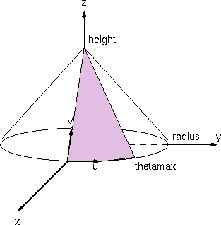
| radius |
The radius of the circular base of the cone in the
xy-plane.
0.0 < radius
|
| height |
The height value defines the position along the positive
z-axis where the apex of the cone lies. If the height is zero
then cone becomes a flat disk.
0.0 <= height
|
| zmin |
The minimum z value is expressed as a percentage of the height.
This defines the minimum latitude line of the patch on the cone.
The surface is bounded by the plane parallel to the xy-plane
at this z height. zmin can be greater than zmax
in which case the surface will be turned inside out.
0 <= zmin <= 1.0
|
| zmax |
The maximum z value is expressed as a percentage of the the height.
This defines the maximum latitude line of the patch on the cone.
The surface is bounded by the plane parallel to the xy-plane at
this z height. zmax can be less than zmax in
which case the surface will be turned inside out.
0 <= zmax <= 1.0
|
| thetamax |
thetamax is specified in degrees. The surface begins
at the x-axis and circles the z-axis by the angle
theta until thetamax is reached.
|
| zslices |
The integer number of concentric triangle strips that are
used to tesselate the cone patch. The strips are separated evenly in
z height.
0 < zslices
|
| thetaslices |
The integer number of radial triangle strips that are used to
tesselate the cone patch. The strips are separated evenly in
angle.
0 < thetaslices
|
| begincap |
Boolean that specifies whether or not to draw a cap at the zmin.
|
Example: Cone Patch
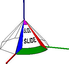
This cone patch was made using the primitives.slf example. The parameters
below define the texture mapped patch, and the wire frame cone
illustrates the default parameter settings.
| Static SLIDE |
Procedural SLIDE |
# Cone Patch

cone con
  surface sTile
  solid SLF_HOLLOW
  shading SLF_GOURAUD
  radius 1.0
  height 0.0
  zmin 0.0
  zmax 1.0
  thetamax 75.0
  texture ( 0 0 ) ( 1 1 )
endcone
|
# Cone Patch
tclinit {
  slide create cone con \
    -surface sTile \
    -solid SLF_HOLLOW \
    -shading SLF_GOURAUD \
    -radius 1.0 \
    -height 0.0 \
    -zmin 0.0 \
    -zmax 1.0 \
    -thetamax 75.0 \
    -texture { 0 0 } { 1 1 }
}
|
Example: Disk
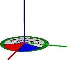
This disk was made using cone primitive in the primitives.slf example. The parameters
below define the texture mapped patch.
| Static SLIDE |
Procedural SLIDE |
# Disk

cone conDisk
  surface sTile
  solid SLF_HOLLOW
  shading SLF_GOURAUD
  radius 1.0
  height 0.0
  zmin 0.0
  zmax 1.0
  thetamax 360.0
  texture ( 0 0 ) ( 1 1 )
endcone
|
# Disk
tclinit {
  slide create cone conDisk \
    -surface sTile \
    -solid SLF_HOLLOW \
    -shading SLF_GOURAUD \
    -radius 1.0 \
    -height 0.0 \
    -zmin 0.0 \
    -zmax 1.0 \
    -thetamax 360.0 \
    -texture ( 0 0 ) ( 1 1 )
}
|
Example: Ring

| Static SLIDE |
Procedural SLIDE |
# Ring

cone conRing
  surface sTile
  solid SLF_HOLLOW
  shading SLF_GOURAUD
  radius 1.0
  height 0.0
  zmin 0.0
  zmax 0.75
  thetamax 360.0
  texture ( 0 0 ) ( 1 1 )
endcone
|
# Ring
tclinit {
  slide create cone conRing \
    -surface sTile \
    -solid SLF_HOLLOW \
    -shading SLF_GOURAUD \
    -radius 1.0 \
    -height 0.0 \
    -zmin 0.0 \
    -zmax 0.75 \
    -thetamax 360.0 \
    -texture ( 0 0 ) ( 1 1 )
}
|
torus
A torus statement describes a portion of a toroidal shell
whose major circular path lies in the xy-plane centered around
the z-axis. The surface of the torus is constructed by
sweeping the center of a circle with a radius equal to the minor
radius along the path defined by the major circle.
| SLIDE Definition |
tclinit Definition |
| torus id
|
| |
majorradius majorradius_float
minorradius minorradius_float
thetamax thetamax_float
phimin phimin_float
phimax phimax_float
phislices phislices_int
thetaslices thetaslices_int
texture ( texture_triple ) [( texture_triple )] ( texture_triple ) [( texture_triple )]
solid solid_flag
surface surface_id
shading shading_flag
lod lod_flag
ribbegin "rib_string"
ribend "rib_string"
|
| endtorus |
|
| slide create torus id \
|
| |
-majorradius majorradius_float \
-minorradius minorradius_float \
-thetamax thetamax_float \
-phimin phimin_float \
-phimax phimax_float \
-phislices phislices_int \
-thetaslices thetaslices_int \
-texture { texture_triple } [{ texture_triple }] { texture_triple } [{ texture_triple }] \
-solid solid_flag \
-surface surface_id \
-shading shading_flag \
-lod lod_flag \
-ribbegin "rib_string" \
-ribend "rib_string" \
|
|
| SLIDE Defaults |
tclinit Defaults |
| torus id
|
| |
majorradius 1.0
minorradius 0.5
thetamax 360.0
phimin 0.0
phimax 360.0
phislices 8
thetaslices 8
texture ( 0.0 0.0 ) [( 1.0 0.0 )] ( 1.0 1.0 ) [( 0.0 1.0 )]
solid SLF_SOLID
surface SLF_INHERIT
shading SLF_INHERIT
lod SLF_FULL
ribbegin SLF_NULL
ribend SLF_NULL
|
| endtorus |
|
| slide create torus id \
|
| |
-majorradius 1.0 \
-minorradius 0.5 \
-thetamax 360.0 \
-phimin 0.0 \
-phimax 360.0 \
-phislices 8 \
-thetaslices 8 \
-texture { 0.0 0.0 } [{ 1.0 0.0 }] { 1.0 1.0 } [{ 0.0 1.0 }] \
-solid $SLF_SOLID \
-surface $SLF_INHERIT \
-shading $SLF_INHERIT \
-lod $SLF_FULL \
-ribbegin $SLF_NULL \
-ribend $SLF_NULL
|
|
| Field |
Description |
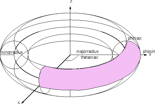
| majorradius |
The radius of the circular axis curve of the torus around
the z-axis in the xy-plane.
0.0 < majorradius
|
| minorradius |
The radius of the circular cross section of the torus.
0.0 < minorradius
|
| thetamax |
thetamax is specified in degrees. The cross section
circle is swept starting at the x-axis and circles the
z-axis by the angle theta until thetamax is
reached.
|
| phimin |
phimin is specified in degrees. When theta = 90, phi
starts at the y-axis and rotates about the
x-axis.phimin can be greater than phimax in which
case the surface will be turned inside out.
|
| phimax |
phimax is specified in degrees. When theta = 90, phi
starts at the y-axis and rotates about the
x-axis.phimax can be less than phimin in which
case the surface will be turned inside out.
|
| thetaslices |
The integer number of triangle strips parallel circling the
circular axis that are used to tesselate the torus patch. The strips
are separated evenly in theta angle.
0 < thetaslices
|
| phislices |
The integer number of triangle strips parallel to the
circular axis that are used to tesselate the torus patch. The
strips are separated evenly in phi angle.
0 < phislices
|
Example: Torus Patch
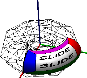
This torus patch was made using the primitives.slf example. The parameters
below define the texture mapped patch, and the wire frame torus
illustrates the default parameter settings.
| Static SLIDE |
Procedural SLIDE |
# Torus Patch

torus tor
  surface sTile
  solid SLF_HOLLOW
  shading SLF_GOURAUD
  majorradius 1.0
  minorradius 0.5
  thetamax 90.0
  phimin 0.0
  phimax 90.0
  texture ( 0 0 ) ( 1 1 )
endtorus
|
# Torus Patch
tclinit {
  slide create torus tor \
    -surface sTile \
    -solid SLF_HOLLOW \
    -shading SLF_GOURAUD \
    -majorradius 1.0 \
    -minorradius 0.5 \
    -thetamax 90.0 \
    -phimin 0.0 \
    -phimax 90.0 \
    -texture { 0 0 } { 1 1 }
}
|
cyclide
| SLIDE Definition |
tclinit Definition |
| cyclide id
|
| |
drawellipse drawellipse_bool
drawhyperbola drawhyperbola_bool
majorradius majorradius_float
minorradius minorradius_float
stringlength stringlength_float
thetamin thetamin_float
thetamax thetamax_float
phimin phimin_float
phimax phimax_float
phislices phislices_int
thetaslices thetaslices_int
texture ( texture_triple ) [( texture_triple )] ( texture_triple ) [( texture_triple )]
solid solid_flag
surface surface_id
shading shading_flag
lod lod_flag
ribbegin "rib_string"
ribend "rib_string"
|
| endcyclide |
|
| slide create cyclide id \
|
| |
-drawellipse drawellipse_bool \
-drawhyperbola drawhyperbola_bool \
-majorradius majorradius_float \
-minorradius minorradius_float \
-stringlength stringlength_float \
-thetamin thetamin_float \
-thetamax thetamax_float \
-phimin phimin_float \
-phimax phimax_float \
-phislices phislices_int \
-thetaslices thetaslices_int \
-texture { texture_triple } [{ texture_triple }] { texture_triple } [{ texture_triple }] \
-solid solid_flag \
-surface surface_id \
-shading shading_flag \
-lod lod_flag \
-ribbegin "rib_string" \
-ribend "rib_string" \
|
|
| SLIDE Defaults |
tclinit Defaults |
| cyclide id
|
| |
drawellipse 0
drawhyperbola 0
majorradius 0.5
minoradius 0.4
stringlength 0.8
thetamin 0.0
thetamax 360.0
phimin 0.0
phimax 360.0
phislices 8
thetaslices 8
texture ( 0.0 0.0 ) [(
1.0
0.0
)]
(
1.0
1.0
) [(
0.0
1.0
)]
solid SLF_SOLID
surface SLF_INHERIT
shading SLF_INHERIT
lod SLF_FULL
ribbegin SLF_NULL
ribend SLF_NULL
|
| endcyclide |
|
| slide create cyclide id \
|
| |
-drawellipse 0 \
-drawhyperbola0 \
-majorradius 0.5 \
-minorradius 0.4 \
-stringlength 0.8 \
-thetamin 0.0 \
-thetamax 360.0 \
-phimin 0.0 \
-phimax 360.0 \
-phislices 8 \
-thetaslices 8 \
-texture { 0.0 0.0 } [{ 1.0 0.0 }] { 1.0 1.0 } [{ 0.0 1.0 }] \
-solid $SLF_SOLID \
-surface $SLF_INHERIT \
-shading $SLF_INHERIT \
-lod $SLF_FULL \
-ribbegin $SLF_NULL \
-ribend $SLF_NULL
|
|
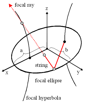
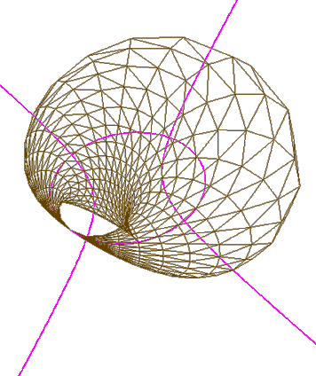
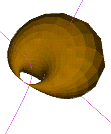
A cyclide statement describes a portion of a cyclide
shell. A cyclide is constructed with an ellipse and a hyperbola that
is confocal to the ellipse. One end of a string, with length
stringlength_float >= 0, is attached to the -x focus of the
ellipse. The string is pulled taught to a point on the ellipse and
then the remaining length of the string is swept around the ellipse by
tracing its focal ray through every point on the hyperbola.
The ellipse is centered at the origin with majorradius in the
x-axis, and minorradius in the y-axis, such that 0 <
minorradius <= majorradius. The string is pulled taught
around the ellipse between angle thetamin_float to angle
thetamax_float from the x-axis. The string is swept
around the ellipse between angle phimin_float to angle
phimax_float.
0 <= phimin, phimax, thetamin, thetamax <= 720.
If thetamin_float > thetamax_float or it phimin_float
> phimax_float, then the orientation of the shell is
reversed.
The integer parameters, phislices_int and
thetaslices_int describe the fineness of the tesselation to be
used when rendering the torus with polygons; phislices_int,
thetaslices_int >= 0 .
[an error occurred while processing this directive]


