|
University of California, Berkeley EECS Dept, CS Division |
||
| Jordan Smith |
SLIDE: Scene Language for Interactive Dynamic Environments |
Prof. Carlo H. Séquin |
| Home | Goals | Publications | People | Gallery | Assignments | Distributions |
In this assignment, you are building slideclip2d, a 2D dynamic SLIDE viewer program which properly clips polygon contours. You will need to implement the following:
The LOD flag controls the quality of rendering. The LOD flag can
be specified in the group, instance, and
object statements.
tclinit {
  proc MouseLOD { x } {
    global SLF_OFF SLF_FULL
    if { x < 0.5 } {
      return $SLF_OFF
    } else {
      return $SLF_FULL
    }
  }
}

object o1 ( ... )
  lod SLF_FULL
endobject

group g1
  lod SLF_FULL
  instance o1
    lod { MouseLOD $SLF_MOUSE_X }
  endinstance
endgroup
The default value is SLF_FULL. The LOD flag can take
on one of the following SLIDE values:
SLF_OFF |
Render nothing. | |
SLF_BOUND |
Render the bounding box only. | |
SLF_EDGES |
Render the edges of the object (wireframe) only. | |
SLF_FULL |
Fully render the object. |
LOD can also be set dynamically using one the global TCL variables (really constants) which are maintained by the viewer: $SLF_OFF, $SLF_BOUND, $SLF_EDGES, and $SLF_FULL.
In a rendering traversal, the actual LOD setting for a node is equal to the minimum of its parent's LOD and its local LOD settings. For example if the parent's LOD is SLF_FULL, then the node's LOD will be whatever is set locally. If a node's LOD is SLF_OFF then it and all of its children are not part of the scene. This effects bounding box calculations because this node now has no geometry and thusly no boundary. The LOD flag can also be dynamic to allow popping branches of the scene graph in and out. Since the LOD flag affects the geometry and can be dynamic, it has a similar effect as a dynamic instance to the update process of viewing a scene. You must modify the Preprocess and Update passes to deal with the LOD flags.
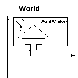
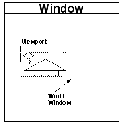
The viewport mapping should transform the World Window (defined by the frustum statement in the SLIDE camera (Xmin Ymin 0) (Xmax Ymax 0)) to fit in the viewport in the largest undistorted way. The world window defines the portion of the scene which the viewer wants to see.
The one complication in this mapping is that it must be split into two transformations:
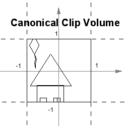
The first transform is a simple translation followed nonuniform scale to fill the canonical square. This transformation will distort your geometry if the world window is not square. That is ok because the second tranform may undo the distortion.
To be able to do the second transformation correctly, you must store the aspect ratio of the World Window to compare against the aspect ratio of the viewport. These aspect ratios will define how to maximal scale the world window into the viewport without distorting its geometry. The following figures show the coordinate systems involved in the viewport mapping.
 |
 |
 |
| World Window | Canonical Square | Viewport |
During rendering traversal, your viewer should check the bounding box of each group or object in the hierarchy against the canonical clipping square. With this check, you should be able to tell if it is necessary to render the group at all. It is not necessary to render geometry which is entirely outside of the viewing area. And if it is necessary to render the group, you should be able to tell if polygon clipping is necessary. If all the geometry of the group is entirely within the viewing area, then none of its polygons need to be clipped.
Your bounding box culling test should return one of the following three results:
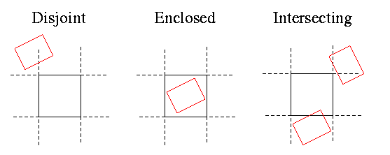
It is a good idea to use the outcodes described in the Cohen-Sutherland line clipping algorithm (p.113 Foley, van Dam, et. al.) to speed up the bounding box checks. The outcodes are (up, down, right, left).
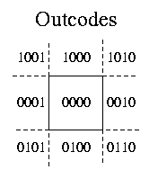
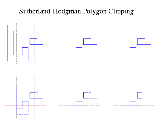
Polygons which may be straddling the canonical clipping square must be clipped using the Sutherland-Hodgman polygon clipping algorithm (p.124 Foley, van Dam, et. al.). We are using a canonical clipping boundary for bounding box culling and clipping in preparation for 3D viewing. The coordinate systems we are using may seem like overkill for this assignment, but they will make processing easier in 3D. The following is an example of the clipping algorithm to refresh your memory:
Make a dynamic scene which shows off LOD, clipping, and bounding
box
culling. Try to make use of the SLF_MOUSE_X and
SLF_MOUSE_Y TCL variables. Also make use of some TK
widgets to add interactivity with the user. You can just make
improvements to your previously generated scene or make a completely
new scene
if you like.
Follow the listed instructions
for as4.
The SLIDE Implementation Specification gives information about the C++ class structure which implements the SLIDE viewer. It also gives an outline of the operation of the viewer.
This page was originally built by Jordan Smith.
Last modified: Tuesday, 28-Sep-2004 10:54:33 PDT