The Design Task
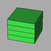
Design rough symbolic floorplans that accommodate the specified building program in one of the given forms. Draw the various rooms as adjacent rectangles of proper dimensions. Since the assignable square footage is about 60% of the gross square footage of each building, you should fill each floor to about 60%; the remainder will be used up by corridors, stairs, elevators, bathrooms, ventilation shafts, cable chases, maintenance closets. Of all those facilities, just concentrate on corridors, stairs, and elevators, for now. Think about the traffic patterns as you lay out the floorplans. There are some prototype computer tools to help you in this task. To the degree that these tools are installed and working, use them as follows:- With the Bubble Diagram Builder convert the room list specifications into a bubble diagram, and then organize this diagram logically so as to show the desirable groupings that are indicated in the adjacency matrix.
- From the Floor Space Manager read in the floorplans for one of the predefined building forms and then move bubbles from the bubble diagram into the floor outlines, thus converting the entire bubble diagram into a set of symbolic floor plans. Also add bathrooms, stairs and elevators. Floor space not explicitly used will become corridor space.
- Call the Floorplan Generator to add automatically generated default doors and windows to the input floor plans, and to flesh out the nonexistent separations between the symbolic rooms into thick walls so that the representation looks more like an architectural floorplan. (To the degree that the tool permits editing operations, you may want to get rid of some of the unnecessary doors.)
- Use the
Schematic Checker Tool
to interactively check the distances between a
few pairs of rooms and see whether they conform to the preferences
expressed in the adjacency matrix.
(We hope to enhance this tool so that it can work in batch mode and can check all the entries in the adjacency matrix.)
Some initial results.
<-- Back to CS 294-5 HomePage
Page Editor: Carlo H. Séquin


