CS 184: COMPUTER GRAPHICS
QUESTIONS OF THE DAY:

|
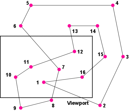
What should be displayed for this
complex, self-intersecting polygon
that extends beyond the viewport ?
Key question:
What is the inside of a polygon ?
(color in what you think is inside!)
|
PREVIOUS
< - - - - > CS
184 HOME < - - - - > CURRENT
< - - - - > NEXT
Lecture #3 -- Wed 1/26/2011.
Key question: What is the inside of a polygon ?
FOIL: Show some prototype polygons, discuss what should be filled in; then define a clean definition and algorithm.
Several possible definitions of "INSIDE":
1.) "PARITY" -- "EX-OR" -- "ON-OFF":
Switch between IN and OUT every time one steps across a single contour edge.
2.) "Non-zero Winding Number":
The polygon contour, seen as a
string loop, cannot be pulled away from a finger stuck at an INSIDE
point.
3.) "Positive (non-zero)
Winding Number":
INSIDE is true if the loops of the oriented
contour caught around probe point travel in CCW direction.
To compute the WINDING NUMBER:
Count ONE UP or ONE DOWN depending whether the oriented contour edge
that one crosses comes from the LEFT or from the RIGHT.
Need to maintain proper polygon topology in clipping! Shark picture; Snake picture.
Why might the orientation of a polygon contour be relevant ? ==>
Backface elimination!
Crucial Concepts from Last Lecture:
Use clean, well-defined abstractions!
Find out what part of a specified
line can be seen in the viewport.
How can that line segment best be approximated on a given
graphics display device? Simplicity and speed versus quality of rendering.
How to save a computer graphics object (save relevant info only:
coordinates,
connectivity, color ...)
==> We need an "interchange
format" (see end of last lecture). This convention defines line segments by their two endpoints.
Linear Interpolation and Line-Clipping
We saw last time that a line may be extending beyond the specified
viewport. To be safe, it should be clipped to the region lying inside
the viewport BEFORE the request to draw that line is sent to the
display device. Plotters may get stuck at the edge of the drawing
surface. In a frame-buffer, adjacent memory may get over-written.
===> ALL GEOMETRY should be clipped to the viewport frame!
Clipping points is easy: just compare with x-, y-bounds of viewport.
Clipping a line is also easy if it is given in parametric form:
Parametric Line Representation:
P(t) := A + t ( B - A
) = A (
1 - t ) + B
t
; with P(0) = A, P(1) = B

Finding t-value of x-clipping edge point: e= [ E - A ] / [ B -
A ]: just compare x-values !
Similarly, for a vertical (x=const) edge: Just compare y-values of endpoints.
WHICH lines must be clipped ? ==> Is there an efficient test to quickly rule out lines that need NOT be clipped ?
LINE Clipping in 2D. (Cohen-Sutherland)
Lines have coherence; thus they can be treated more
efficiently
than random points.
Convexity of the window also helps:
==> We need to consider only
the endpoints of the line !
Do some region checks for trivial accept/reject decisions:
Whole window plane is divided into 9 regions by extending window edges.
Assign a "4-bit outcode" to the end vertices of the line segment.

1.) Trivial accept, if both
end codes = 0000;
2.) Trivial reject, if both
end codes have one bit in common;
e.g. "above", both have 1xxx. This can be done efficiently by forming
AND codes of the two
endpoints.
3.) If no trivial accept or reject, clip
line against window, one edge
at a time. The clip point at window edge (B0)
replaces the outer, clipped point (B).
Continue on same line until obtaining a successful accept/reject test.
This process is particularly efficient if the window is a small part
of the whole scene.
Use the above line-clipping algorithm based on linear interpolation!
Simple Polygon Morphing by Linear Interpolation
Since polygon2 (A#2) is created from polygon1 (A#1) by simply moving
vertices, both polygons have contours with the same number of points;
and we thus have a direct one-to-one correspondence between pairs of
points.
The morphing parameter defines an intermediate polygon by
interpolating between the positions of corresponding points. For each
point the intermediate position is given by:
P(t) := A + t ( B - A
) = A (
1 - t ) + B
t
; with P(0) = A, P(1) = B; t = interpolation/morphing parameter.
For a good, pleasing, smooth morph, do not move vertices wildly across
opposite polygon edges, and keep some semantic identities in place.
POLYGON Clipping. (Sutherland-Hodgman)
If we are just concerned with displaying outlines of polygons as in
assignments A#1-A#3, then clipping individual line segments is all that
is needed. However if we want to display filled-in, shaded polygons, then we need
to present to the display device a properly oriented, closed
(water-tight) polygon contour that lies within the viewport. Thus the
polygon as a whole has to be clipped in a coherent manner, preserving
the winding number around all displayed points.We clip the polygon
sides that cross the viewport frame with the above
line clipper;
but we also need to fill in missing
boundary pieces in order to close
the polygon
in such a way that it can be filled (painted) properly.
Conceptual issue: What is inside a polygon ? ===> See previous discussion.
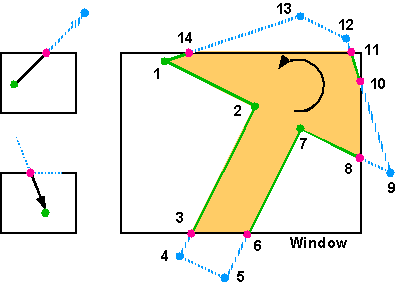
Clip the polygon against one window edge at a time to
produce
proper corners.
Work with the vertices of the polygon and with conceptual rubberbands
between them.
Pipeline the whole process.
Example #1: simple polygon: "Arrow"

Basic concept: Walk
around contour,
parametric clip of any edge that
crosses from inside to the outside,
"rubber-banding" the parts outside the window
onto
the window edge;
parametric clip of the edge that crosses back inside.
Implementation: Do this
for each (extended) window edge in sequence.
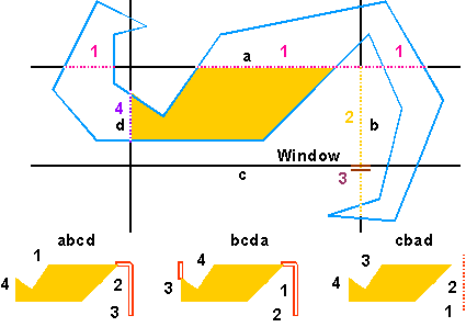
Watch out: sequence in which we deal with the window edges does matter.
Example #2: complicated polygon "Double-Hook"

-- show what can happen: Spurious
double edges !
Now we know how to preprocess a 2D polygon and then how to sample it to obtain an adequate rendering on a graphical display device.
What else do we have to do if our polygon is a general polygon in 3D ?
And what else is required if we have a 3D scene composed of many different polygons ?
Quick Overview of the Classical Rendering Process
Now suppose we have a scene composed of many complex polygons in 3D. How do we a get picture of it?
In the classical graphics rendering pipeline, each object (polygon) is individually modeled, transformed, processed,
and rendered.
The Various Coordinate Systems:
World
to screen transforms - Overview
(This is valid in some form for all rendering environments).
Master Space, Model Space, Symbol Space:
Used to define hand-designed or procedurally-generated (master) objects
or "symbols".
There may be a hierachy of such model spaces,
but at the lowest level (at the "leaves"), the geometry is "flat"
(non-hiererchical) -- as in A#1 and A#2.
World Space, Scene Space:
Used to composite the overall scene.
Hierarchy of (instantiated,
transformed) groups and objects.
(Watch out in what sequence the transformations are applied !)
Rendering Space, Eye Space, Camera Space:
Defines from where we want to view the scene, and what lies outside the
viewing angle.
We form a new coordinate system with its origin in the eye (or in the
camera lens),
and with its z-axis in the looking direction; we also form an "up"
direction for the display.
The projection screen (retina,
film) is perpendicular to that
direction,
and lies at some distance;
it contains a rectangle (the "window")
that defines what part of the
overall scene will be rendered.
From the eye we do a point projection
( perspective projection )onto
the screen;
alternatively, we can do a parallel
projection from the direction of
the eye.
In either case, we may clip away stuff that is too close or too far
away.
Image Space:
This is the 2D space of the projection
screen.
Often the scene hierarchy has been lost; it is now just a flat set of
lines,
polygons,
etc.
The drawing primitives may have been (re-)arranged into (display)
segments;
these may be grouped for similar treatment (color, transparency,
visibility,
spatial location).
This set may then be clipped by the window (rectangular area in the
projection
plane).
Normalized Device Coordinates:
Fit everything into a unit square for easy manipulation and mapping
onto the screen
or into a rectangular viewport (= "window" to the laymen) on the screen.
This is achieved through a simple coordinate transformation of all
elements inside the window.
This gives us device independence
!
Screen Space:
Pixels or x,y addresses of the actual display device.
Dots, lines, filled areas, etc ... are expressed typically in integers
> 0.
Y-axis may be upside down (counting pixel rows downward).
More on all this in the next few weeks ...
Reading Assignments:
Study: ( i.e., try to understand fully, so that you can answer
questions
on an exam):
Shirley, 2nd Ed: Ch 3.1, 3.3, 3.5;
Shirley, 3rd Ed: Ch 3.1, 3.3, 8.1.1.
Skim: ( to get a first idea of what will be discussed in the future,
try to remember the grand ideas, but don't worry about the
details yet):
Shirley, 2nd Ed: Ch 3.6;
Shirley, 3rd Ed: Ch 8.1.2.
Programming Assignments 1 and 2:
Both must be done individually.
Assignment #1 is due (electronically submitted) before Friday 1/28, 11:00pm.
Assignment #2 is due (electronically submitted) before Friday 2/4, 11:00pm.
Accounts for which we do not see a web page and a posted Assignment #1 by Monday, January 31 will be closed.
PREVIOUS
< - - - - > CS
184 HOME < - - - - > CURRENT
< - - - - > NEXT
Page Editor: Carlo
H. Séquin