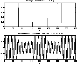
Figure 7: Passband PAM Modulation
Here the basic idea is to use as the carrier signal a pulse train. The choice of this pulse train can be quite interesting from the standpoint of energy and spectral content consumption. One can use square pulses, or raised cosine pulses, or sync function (Nyquist) pulses. For simplicity, let us talk about square pulse trains. The characteristics of the pulse train that can be varied are: its amplitude or width or position of leading edge. We will talk about the first two ideas; the modulation schemes which do this are called Pulse Amplitude Modulation (PAM) and Pulse Width Modulation (PWM) respectively. The figure 7 shows what is known as a passband PAM, in that the PAM pulse train is actually also multiplied by a carrier frequency sinusoid, so as to enable transmission at a higher frequency.

Figure 7: Passband PAM Modulation
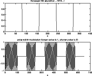
Note that this basic scheme can be made more sophisticated by using several amplitude levels: for example one can group the bits into groups of 2, ie. 00, 01, 10 and 11 and have four different amplitude levels for each of these groups. This is referred to as Quadrature Pulse Amplitude Modulation (QPAM or QAM for short). QAM actually is used for alphabets of size other than 4. Thus for example. 2400 Baud full duplex modems use 16-QAM (corresponding to grouping 4 bits together). 9600 Baud, 14,400 Baud, 28,800 Baud modems use 32-QAM, 128-QAM and 1024-QAM respectively (along with something known as trellis coding). PWM is illustrated in figure 8. The circuitry required to generate this is complicated, but it is extremely conceptually important since there is good reason to believe that neurons transmit information using PWM spike trains.

Figure 8: Showing PWM modulation