|
|
A 2nd generation prototype was built with the following advantages over the previous version:
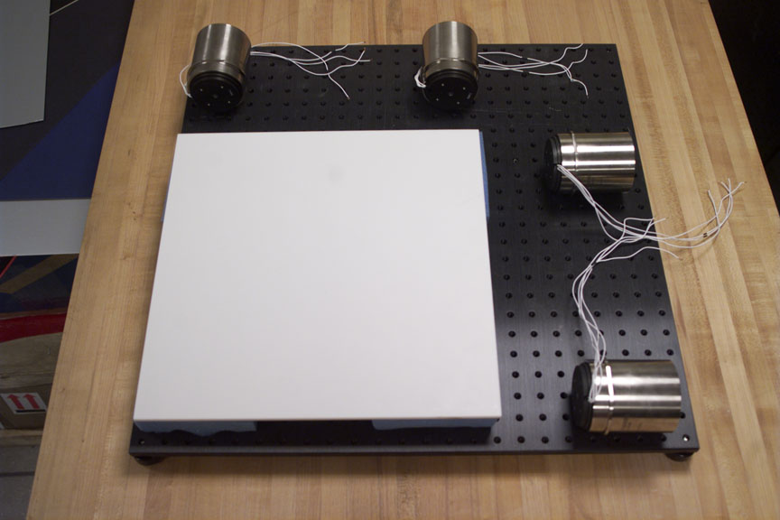
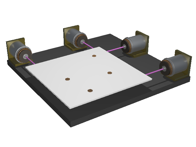
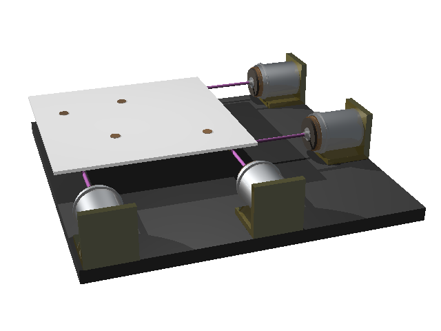
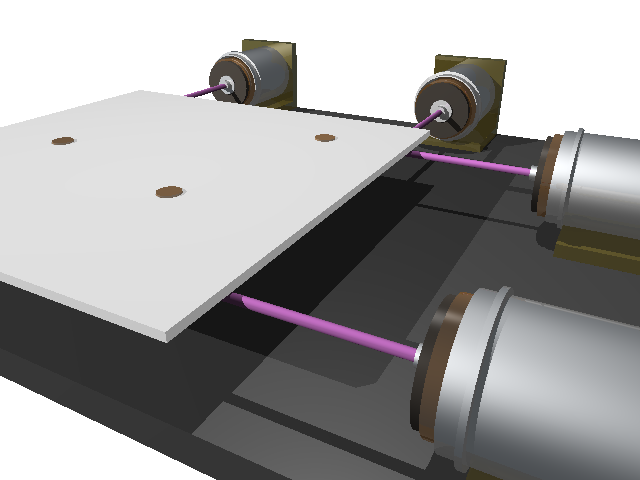
In the old actuator design, motor pairs X1X2 and Y1Y2 were attached at opposite sides of the table (left); in the new design, these pairs actuate from the same side, reducing the system's footprint.
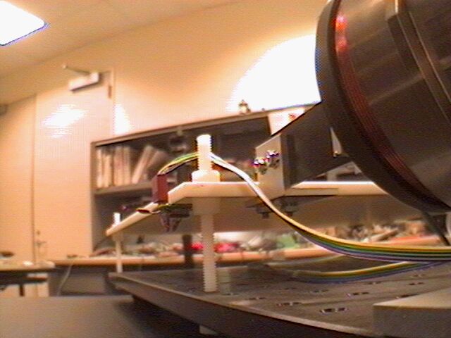
All components are mounted on a sturdy Edmund Scientific 24''x24''x1/2'' aluminum breadboard, with 1/4"x20 holes on a 1" grid. The plate is a 1/4" sheet of Corian kitchentop material, chosen for its flatness, rigidity, and light weight. Since the new table has four times more area and is twice as thick as the previous one, its effective weight has grown eightfold to roughly 3.5 lb. To avoid a vertical strain on the motor's shafts, we installed four 1/4''x20 threaded nylon rods under each of the table's corners; these double as linear springs in the table's 3 horizontal dof's. The new linear actuators are BEI-KIMCO LA-30-43-000A voice coils, with a peak output force of 100 lbf. The motors are mounted horizontally with 3/8''-thick aluminum angles. The motors apply force to the table via polyurethane shafts. A consumer audio power amp (75 W x 4) is used to amplify the signal sent from the signal-generation hardware to the motors, which are wired in series with four 2 ohm x 50 watt resistors. Two Analog Devices' ADXL210EB accelerometers are glued to the table's corners; each can measure two perpendicular accelerations. This signal is fed back to the PC via an interface board so the instantaneous center of rotation (COR) can be recovered. Photos (thanks to Paul Debevec) of the unassembled prototype are shown below:
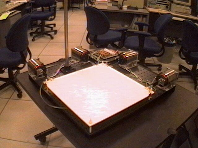
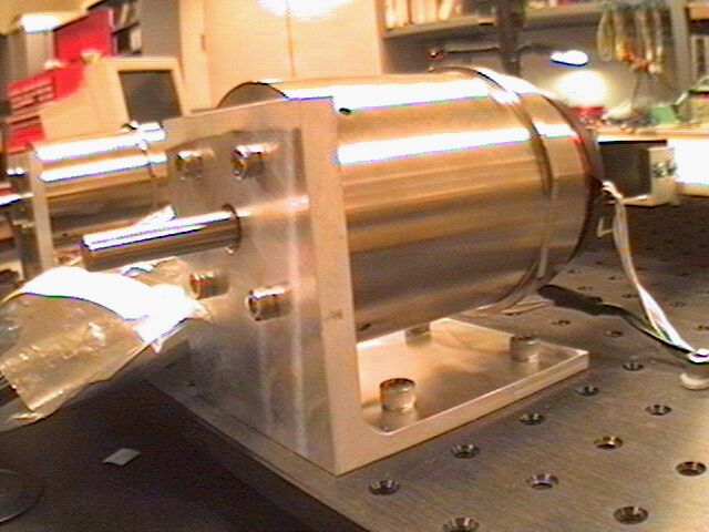
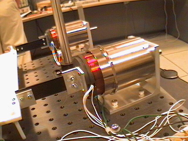
The pictures below depict the new prototype in its completely assembled state.
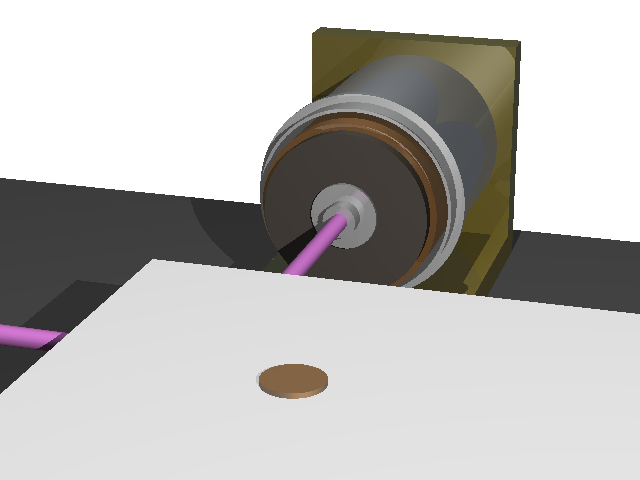
3d ModelingA CSG model of the new prototype was constructed with Moray v3.1 to aid in the design process. A few views ray-traced with POV-Ray v3.1 are shown below (the associated files are here). Click on the pictures for larger versions.
|
| © 2000 Dan S. Reznik, <dreznik@cs.berkeley.edu> |