|
|
Block Diagram
PCB Design
FirmwareFirmware was written for the PIC16c73 using the excellent PIC-C v7.81 ANSI-C compiler donated to us all the way from Alderly, Australia by Hi-Tech Software. The firmware is divided into three files, available for download: * firmware.h -- constants and data structures The complete set of firmware files (along with the .hex and .obj files produced by the compiler) are grouped into firmware.zip. Device DriverAll of our PC-side software was written over Red-Hat Linux version 6.0 (linux kernel 2.2.x). The device driver required parallel port access, which is simplified (and enabled to non-superusers) by installing (/sbin/insmod) the parport, parport_pc, and ppuser kernel modules, in that precise order, prior to running the device driver.We wrote an API -- parallel.h -- which abstracts the ppuser interface to a few simple calls. The sets of functions available thru the device driver are condensed in a single API file, board.h. A GUI-driven program has been written to test the API. The set of files comprising this program have been grouped into board.zip. The main user interface window is shown below -- it allows the user to interactively set (and recover) all parameters global to the signal-generation function of both PIC-A and PIC-B.
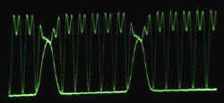
Signal Generation Essentially, the desired output signal is a sin(t)+cos(2t) waveform shaped by an attack-sustain-decay envelope. Actual output measured with an oscilloscope is shown below:
Data Acquisition With the table in motion (e.g., driven by four independent signals as in the above), the 4-channel acceleration samples cab be visualized in real time by a special program, and fit to smooth curves, as shown below:
The parameters recovered from the curve fitting step (4 for each wave, for a total of 16) are then used in the real-time estimation of the shaker table's center of rotation; a snapshot of the sensor measurements along with the position of the COR appears below:
|
| © 2000 Dan S. Reznik, <dreznik@cs.berkeley.edu> |