More important than the particular details of the RS6000/590 is that they illustrate many of the issues we will encounter over and over in other aspects of parallel computing. In order to write fast code on the RS6000/590, or any machine, one should exploit:
Much of the detail of the following discussion is taken from "Exploiting functional parallelism of POWER2 to design high-performance numerical algorithms", R. Agarwal, F. Gustavson, M. Zubair, IBM J. of R&D, v. 38, n. 5, Sept 94 (see reader). The whole issue of this journal discusses details of the RS6000 architecture, and how to optimize programs for it. Many of these articles are on-line, including a description of IBM's numerical subroutine library ESSL. There is also a great deal of material available on tuning the performance of code. For the truly ambitious, a performance monitor is available, which uses special purpose hardware to measure how well each part of the central processing unit (CPU) is performing (ask if you are interested).
The table below shows the stages one might go through in attempting to write a fast matrix multiplication routine for the RS6000. The first stage is to figure out the maximum speed at which the machine runs. We will measure success by how close to this peak speed we can get. The first line in the table is the clock rate, and the second is the peak speed. Since each floating point operation takes 1 cycle, and there is 4-fold parallelism in the machine (2 floating point instructions per cycle times 2-fold pipeline parallelism, as we explain further below), the maximum machine speed is 4 x 66.5 Mflops = 266 Mflops. The other lines give the computation rate for 64-by-64 matrix multiply, computed using several algorithms and compiler options.
Unblocked matmul refers to Algorithm 1 in Lecture 2. DMR is a public-domain routine optimized for the RS6000. Finally, ESSL's dgemm is IBM's proprietary optimized matrix-multiply (for double precision data). f77 is the name of the Fortran compiler, and the strings following f77 are various compiler optimization flags.
When unblocked matmul with no optimization is used, the speed is a disappointing 4.5 Mflops, a small fraction of peak speed. Optimization level "-O2" attains 65 Mflops, which is approximately the clock speed. This means that the machine is doing just 1 floating point operation per cycle, rather than the maximum 4. Optimization level "-O3 -qhot" without the "-qstrict" option is one of the most aggressive levels of optimization; when using it, the compiler prints a warning that it may change the semantics of the code in its pursuit of a fast version of the code. DMR compiled this way gave erroneous answers for n>64, and still got only 186/266=70% of the peak machine speed (this was a bug, not a feature, and is meant as an early warning that leading edge technology is not always as reliable as less ambitious technology!).
          Clock rate:                       66.5 MHz
          Peak speed:                      266   Mflops

          Unblocked matmul, f77:             4.5 Mflops
          Unblocked matmul, f77 -O2:        65   Mflops
          Unblocked matmul, f77 -O3 -qhot:  92   Mflops

          DMR             , f77 -O2:       152   Mflops
          DMR             , f77 -O3 -qhot: 186   Mflops (buggy for n>64)

          ESSL dgemm      , f77 -O3 -qhot: 240   Mflops
There is yet another optimization level, not illustrated here, which would "pattern match" to discover that the unblocked implementation was really doing matrix multiplication, and replace everything by a call to ESSL's dgemm, which then nearly attains peak speed. This kind of optimization technique is clearly limited in generality.
This table illustrates that one cannot yet expect most compilers to take naive code and produce object code that fully exploits the speed of the machine, expect for a very few special cases where the compiler can recognize an entire algorithm (such as matrix multiply) and replace the user's program with a call to a preexisting library subroutine. Compilers for high-performance machines are a current subject of research, to which we will return in a later chapter. Some research compilers do attack the problem of automatically optimizing code for particular cache organizations. For example, see the SUIF compiler work at Stanford, such as "The Cache Performance and Optimizations of Blocked Algorithms" by M. Lam, E. Rothberg and M. Wolf. See also the working on "Hierarchical Tiling for Improved Superscalar Performance", by L. Carter, J. Ferrante and S. Flynn Hummel.
Now we begin discussing the RS6000/590 in more detail, and explain how one would write a matrix-vector multiply routine. Along the way we will learn more about how memory hierarchies work, and how to best use them. Yet more details about the RS6000/590 may be found in the IBM document Algorithm and Architecture Aspects of Producing ESSL BLAS on POWER2, especially the section on BLAS-2 Implementation.
Cycle              1        2           3           4           5

Multiplication   b1*c1    b2*c2       b3*c3       b4*c4
Addition               (b1*c1)+d1  (b2*c2)+d2  (b3*c3)+d3  (b4*c4)+d4
Thus, a 2-stage pipeline can perform n operations in n+1 steps. Since 1 "operation" in this case consists of 2 floating point operations, this means 2*n flops are performed in n+1 cycles. Without pipelining, it would take 2*n cycles to perform the 2*n flops, meaning that the speedup is 2*n/(n+1), or nearly 2 for large n.
For this to work, it is important that these operations be independent, i.e. that none of bi, ci, or di is computed as a(i-1) in the previous operation. In this case, the data would not be available in time for the pipeline to use it, and there would be delays (unused cycles).
More generally, an s-stage pipeline can work on as many as s independent operations at a time, taking s+n-1 cycles to finish n operations:
Cycle      1       2       3  ...   s         s+1     ...  n        ...   s+n-1

Stage 1   op1     op2     op3 ...  ops       op(s+1)  ... opn       ...
Stage 2           op1     op2 ...  op(s-1)   op(s+2)  ... op(n-1)   ...
  ...                         ...
Stage s                       ...  op1       op2      ... op(n-s+1) ...   opn
Without pipelining, the same sequence of operations would take s*n cycles, meaning that the speedup is s*n/(s+n-1), or nearly s when n is much larger than s. Pipelining is a very common way to get speedup, because it does not require multiple copies of the hardware (in this case, one adder and one multipler are all that is needed), and so is ubiquitous in the RS6000/590, in other machines ranging from PCs to supercomputers, and in many factories since the days of Henry Ford.
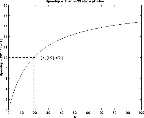
We just said that when the number of operations n is large compared to the pipeline length s, the speedup s*n/(s+n-1) is nearly s. But for smaller n, the speedup drops. A common way to express this fact is with the quantity n_{1/2}, read "n-one-half", which is the minimum value of n for which the speedup is half its peak value s:
s * n_{1/2} / (s + n_{1/2} - 1) = s/2 or n_{1/2} = s-1
This is shown in the following plot:
The concept of "minimum problem size to reach half-peak performance" has become popular for other problems not solved by a single pipelined operation, because their speedup plots often appear as in the above graph: speed increases for larger problem sizes. For example the LINPACK Benchmark, defines n_{1/2} to be the smallest matrix size for which Gaussian elimination runs at half its peak performance.
The fused-multiply-add instruction has one other interesting property: it is performed with one round-off error. In other words, in a=b*c+d, b*c is first computed exactly to quadruple (128 bit) precision, if b and c are double (64 bit) precision, then d is added, and the sum rounded to a. This use of very high precision is used by the RS6000 to implement division, which still takes about 19 times longer then either multiply or add. Square root takes 27 times longer. The fused multiply-add may be used to simulate higher precision cheaply. All arithmetic conforms to the IEEE Floating Point Arithmetic standard which we will discuss later (see the notes on floating point by W. Kahan, or the two papers on floating point arithmetic in Volume 6 of the class reference material.
To summarize: to get speed out of the RS6000/590 FPU, one's algorithm needs to execute a sequence of independent operations, each of which is a multiply-add operation a=b*c+d.
Here is a brief summary of the main properties of the RS6000/590 cache; the details follow. The cache is 256 KB long, with 256 bytes (32 8-byte double-words) per cache line. It is 4-way set associative. Its write policy is store-back with LRU. It is dual-ported and nonblocking. A cache miss has a latency of 14-20 cycles and takes 8 cycles to fill a cache line. There is a quad load/store instruction.
Here are the details. The cache, or fast memory, is 256 KB long. It is read or written to slow memory in 256 byte chunks called cache lines. A load instruction trying to fetch the data stored in a memory location and put it into a register first checks to see if the data is in the cache. If it is, the cache supplies the requested data in one cycle; this is called a cache hit. Otherwise, there is a cache miss, and a delay of 14-20 cycles before an entire cache line containing the desired data starts arriving, 32 bytes/cycle, from main memory (another pipeline!). Therefore it is much more efficient if an algorithm processes all 256 consecutive bytes (32 consecutive double-words) in a cache-line, since it pays for them to be moved from main memory anyway, rather than only using one or a few words and ignoring the rest. This is called exploiting spatial locality, or using all the data located close together in memory. Movement of data between other levels in the memory hierarchy usually occurs in large chunks (such as pages between disk and main memory), so spatial locality is an important aspect of algorithm design.
As long as there is space in the cache when there is a cache-miss, cache-lines are fetched and stored in cache. The cache is organized in 256 sets with 4 cache-lines per set. 8 consecutive bits of the memory address being fetched are used to pick which of the 256 sets a cache line is to occupy. Since there are 4 lines in a set (4-way set associativity) as many as 4 lines with the same 8 bits in their addresses can simultaneously be in cache.
When a set fills up, and a fifth cache line is fetched, one of the lines currently in the set must be selected to be evicted, or removed from the cache. The one selected is the one Least Recently Used (LRU) - a counter is associated with each cache line to keep track of this - and it is then written back into slow memory. This is an illustration of why an algorithm should exhibit temporal locality, or reuse of data recently used: as long a datum is used frequently enough, it is guaranteed to remain in cache via the LRU mechanism.
When a word is written, only the cache is updated, not the slow memory. The modified cache line is marked as dirty by setting a bit. When a dirty cache line is evicted, it must be moved back to slow memory (clean cache lines can just be overwritten, which is faster). This is called a write-back policy, since slow memory is updated only when a dirty cache line is evicted, in contrast to a write-through policy, where slow memory is updated on every write (this is slower, since it accesses slow memory more often).
The cache is dual-ported and nonblocking. This means that if one cache read misses, and a 14-20 cycle delay ensues while the missing cache line is fetched from slow memory, then there is a second port on the cache which can continue functioning independently and keep the FPU supplied with data.
A load instruction moves an 8-byte word from the cache (if there is a cache-hit) to a register in one cycle. A store instruction moves the data in the opposite direction. A quad load/store instruction moves 2 consecutive 8-byte words from cache to 2 consective memory locations in 1-cycle, which is twice as fast as a standard load/store.
        Algorithm 1                                Algorithm 2

     for i = 1 to 1024                           for j = 1 to 1024
        for j = 1 to 1024                           for i = 1 to 1024
            A(i,j) = A(i,j) + B(i,j)                   A(i,j) = A(i,j) + B(i,j)
        end for                                    end for
     end for                                    end for
These algorithms differ only in the order of their two nested loops, but
they differ greatly in performance because of differing spatial locality.
Initially, arrays A and B are stored in main memory.
A and B each occupy 8*1024^2 = 2^23 bytes,
whereas the cache is only 2^18 bytes long, so they do not fit in cache.
Since the matrices are stored by rows, Algorithm 1 accesses consecutive
memory elements in the innermost loop, thus exhibiting good spatial
locality, whereas Algorithm 2 accesses memory elements 8*1024 = 2^11 bytes
apart, and so in different cache lines. Thus, in Algorithm 2 there will
be 2 cache-misses on every pass through the inner loop
(one for A(i,j) and one for B(i,j)), whereas for Algorithm 1
there will only be 2 cache misses for every 32 consecutive values of j in the
innermost loop.
In other words, Algorithm 2 will probably have 32 times as many cache misses
as Algorithm 1, and in fact twice as many cache misses as floating point
operations.
Since one cache miss takes at least 14 cycles, or 14 times as long as a
floating point operation, Algorithm 2 will be many times slower than
Algorithm 1.
T0 = Y(I) 	! load 24  Y elements
T1 = Y(I+1) 	! in 24 FPRs (floating point registers)
        ...
T23 = Y(I+23)
DO J = J1, J1+JBLK-1
	XJ = X(J)	! load an element of X
	F0 = A(I, J)	! one Quad-Load loads
	F1 = A(I+1,J)	! both F0 and F1 in one instruction
	T0 = T0 + XJ*F0	! update Y(I)
	T1 = T1 + XJ*F1	! update Y(I+1)
	   ...		! update other 22 Y(.) values
	F0 = A(I+22,J)
	F1 = A(I+23,J)
	T22 = T22 + XJ*F0
	T23 = T23 + XJ*F1
ENDDO
Y(I) = T0 	! store Y elements
Y(I+1) = T1 	! after the loop
     ...
Y(I+23) = T23
Let us explain what is going on:
Here is a slide of the performance of matrix-vector multiplication (dgemv). ESSL refers to IBM's optimized routine, and LAPACK [sic] refers to the naive algorithm with 2 nested loops, which may be found here. Note the drop in performance when the dimension hits around 180, which is the largest size matrix that fits in the cache. In other words, the performance for smaller matrices has been measured assuming all the data is initially in cache. The drop occurs because it is impossible to hide the slower speed of the slower memory by blocking techniques, as discussed in Lecture 2.
In contrast, consider the performance of matrix multiplication in the following graph. The performance stays pegged at close to the peak speed, even for matrices too large to fit in cache, because the blocking technique in Algorithm 3 of Lecture 2 can hide the slower speed of the slow memory.
After Assignment 1 is over, we will discuss more systematic ways of optimizing performance on the RS6000/590 and other architectures.