1. Overview
The next few labs introduce concepts in electronics and IoT and cover a wide range of applications. Using a microcontroller (MCU), we automate measurements and send results via the Internet to the “cloud”, where they can be processed, archived, and accessed from anywhere in the world.
The module is organized as follows:
-
Characterize the solar cell again, but this time the MCU does all the tedious work.
-
Send measurement results wirelessly to the “cloud” for archiving and plotting.
-
Use low-power design techniques to build a solar-powered weather station.
Not each lab segment takes the same amount of time. You are encouraged to start the next segment early if you finish early and may complete your work in a later session if you need more time. Make sure that at the end of the allocated three sessions you complete all checkups!
2. Prelab
In this lab we will set up MicroPython on the MCU and learn how to run programs and work with sensors (INA219) to automatically take measurements.
2.1. Microcontroller (MCU)
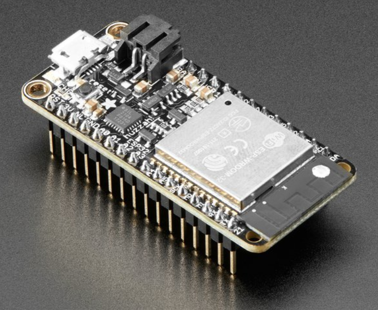
MCUs (follow the link and read the document!) are just like other computers except smaller. Instead of keyboards and displays they have interfaces to electronic sensors and actuators. Figure 1 shows the MCU used in this and subsequent labs. At the core is an ESP32 CPU. Just like the INA219 we use the ESP32 mounted on a breakout board that, in addition to the CPU, also includes a USB connector (for programming), WiFi antenna, etc.
Read the board description and answer the following specifications (with units):
-
Clock rate:
-
Size of flash memory:
-
Size of SRAM:
-
Maximum voltage on any logic pin:
Never connect a voltage higher than this value to any logic (as opposed to supply) pin of the ESP32!
Write a program that blinks the LED on the ESP32 breakout board at a rate of 1.5Hz, with equal on and off times.
2.2. INA219
In this lab, we will use an INA219 to automatically measure the current and power from the solar cell. The INA219 communicates with the MCU using the I2C bus. I2C uses only two wires for communication. Up to 127 devices can be attached to the same bus and a wide range of I2C compatible sensors is available. The MCU uses an address to select a device for communication, e.g. requesting a sensor result.
Download the datasheet from the TI website and answer the following questions:
-
What is the “Absolute maximum rating” of the supply voltage?
-
What is the power supply operating range?
-
What is the minimum storage temperature?
-
What is the maximum ADC conversion time for 11-Bit accuracy?
-
What is the maximum quiescent power supply current?
-
By what factor does the maximum supply current decrease if the device is put into power-down mode?
-
What is the range of I2C addresses for which the INA219 can be configured? State your answer as decimal numbers! …
-
What is the ESD rating of the pins of the INA219 for the human body model?
You may be surprised by the last answer. Electronic devices are extremely sensitive to electrostatic discharge which happens when e.g. a human who is not grounded (electrically connected to earth ground) touches a device. Although the voltage may be very high, the total energy is not and presents no danger to a human. However, the components (e.g. transistors) inside the electronic circuit are very small (often only a fraction of a micron, 10-6m, on a side), and are easily damaged by electrostatic discharge. Manufacturers add special circuitry for protection. However, it is always a good idea to be careful and avoid electrostatic discharge.
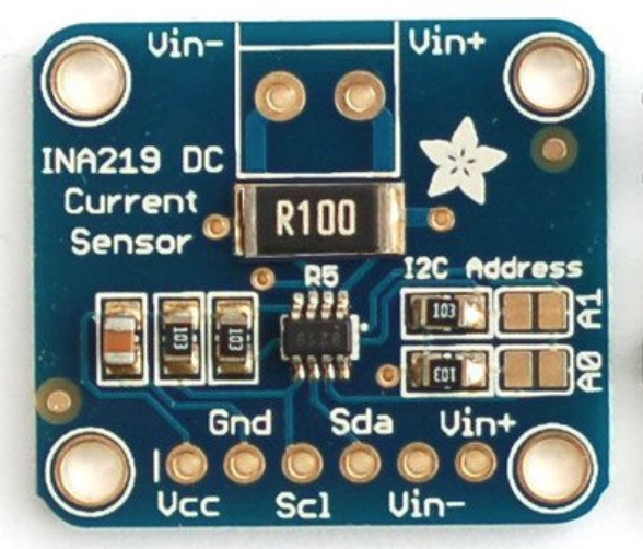
Since the INA219 is only available in tiny SOT packages which are not compatible with solderless breadboards, we use a so-called “breakout board” for adaptation (Figure 2). Consult the manufacturer information at https://www.adafruit.com/product/904. In addition to the INA219, the board also includes a current sensing resistor.
-
What is the value of the current sensing resistor on the board?
-
What is the maximum current that can be measured?
-
What is the current resolution in 12-Bit ADC mode?
-
What current sensing resistor value is required for a ±8A maximum current range?
2.3. Automatic Solar Cell Characterization with MCU
At last we have all the pieces to automate solar cell characterization (or other measurements) with an MCU.
In the space below, draw the circuit diagram of the ESP32 connected to the INA219 breakout board, solar-cell, and potentiometer load.
Based on the example discussed in the lecture, write a program to continually measure the solar cell voltage and current with the INA219 and print these values along with the value of the potentiometer and power delivered by the solar cell including units.
Your output should look as follows:
3.42V   23mA   149Ohm    78.7mW
4.89V  102mA    48Ohm   498.8mW
...
Save the program (solar1.py) on your computer and submit it as part of your prelab.
3. Lab
3.1. MicroPython
Install the MicroPython interpreter on the ESP32 following the instructions in the prelab.
Then upload the blink program you wrote and show the blinking light to the instructor.
3.2. Solder INA219 Header
Solder the 6-pin header and 2-pin screw terminal to the INA219 breakout board following these instructions. Leave the I2C address at its default, 0x40.
Before soldering, watch the demo by the instructor. Proceed carefully as to not damage the board and do not hesitate to ask questions. Beware: do not touch the hot end of the soldering iron!
3.3. Build Circuit Prototype
Wire the circuit and measure the solar cell voltage and current both with the INA219 and the DMM for verification. Show your results to the instructor and be ready to answer questions about your circuit and program.