1. Safety
The laboratories in this course are designed to use voltages less than 30V. Such low voltages when touched do not usually deliver sufficient energy to the human body to cause harm. However, the equipment we are using is capable of generating higher voltages and is connected to the high voltage household current grid (110V … 240V) that is harmful when touched. Follow these precautions when working in the lab:
-
Turn off the power when modifying a laboratory setup or performing manipulations that could expose you to high voltage or cause components to overheat.
-
Verify that it is safe to do so before touching a laboratory setup. Consult an instructor when in doubt. Use laboratory equipment (e.g. a voltmeter) to determine voltage levels.
-
Circuit components can heat up, e.g. due to a short circuit. Exercise care when touching.
-
Soldering irons are hot! Be careful not to touch the tip or shaft, and also keep it away from desk surfaces or combustible materials.
-
Solder contains lead, use proper ventilation and do not to inhale fumes.
-
Wires, tools, and equipment can have sharp edges or be heavy. Take appropriate precautions, such as wearing gloves.
2. Lab Organization
The document you are looking at are the instructions for the first laboratory in EE 49. You will use similar instructions for all labs. The instructions include tasks that need to be completed before the laboratory (marked “Prelab”), and the guide for what you will be doing in the laboratory (heading “Lab”). Record the answers to the prelab questions and your measurement results directly in the instructions and upload them to gradescope before the lab. Bring a printout of the lab instructions with your calculations to the actual lab so you are ready for the experiments.
-
Preparation (“Prelab”): Download the instructions and read the entire document to be ready for the laboratory. For many labs you will be asked to read datasheets, write code, and design the circuits you will be building and characterizing. Complete all these assignments before the lab and make sure to copy all your results to a printed copy of the lab instructions or on separate sheets appended to the instructions. Please get help in office hours before the lab if you have questions. You will not be permitted to to attend the lab if you do not come on time and fully prepared.
-
Laboratory: Follow the instructions and perform all required measurements. Ask the lab instructor for help if you have problems with equipment, parts, or your circuits. The instructor will not answer pre-lab questions during the lab. Please use office hours before the lab for this purpose.
-
Checkoff: At key milestones, the instructions ask you to demonstrate your working setup and show your results to the instructor to get credit for the lab.
-
Report: Collect your measurement results, interpretations, etc. on the printed lab instructions and add additional sheets as needed. Before leaving, ask the instructor to verify your results and be ready to hand over the completed report if asked to do so.
3. Parts
At the start of the course you and your lab partner will receive a set of parts that you will use throughout the course. Some parts will be distributed in later labs and some are available in the lab for use when needed. Be careful not to loose or damage the parts you receive!
4. Prelab
Find the voltage or current shown by the meters in Figure 1. Assume the meters are ideal. All voltage sources are 3V, current sources 5mA, and resistors 5kΩ. Include the correct sign and unit with your results.
| Circuit | Meter reading |
|---|---|
a |
|
b |
|
c |
|
d |
|
e |
|
f |

V and A represent voltage and current meters, respectively.In your lab kit you find a small solar cell. Neat, it will cover all your energy needs. You go off the “grid” and save thousands!
Do not believe me? Well, I do not blame you. But what could you power with that small solar cell? Let’s find out by measuring the power it delivers. Unfortunately, our meter measures only voltage or current, not power. Calculate the power delivered by the solar cell in the two situations in Figure 2. Assume that the meter is ideal.
| Circuit | Meter reading | Power delivered |
|---|---|---|
a |
4.5V |
|
b |
120mA |

Well, that’s disappointing. Let’s try something else. This time we connect a resistor across the solar cell and measure the voltage across and current through the resistor. What is the power delivered by the solar cell to the resistor?
| Voltage across resistor | Current through resistor | Power delivered |
|---|---|---|
3.8V |
40mA |
The power delivered by the solar cell depends on the resistance. So let’s use an adjustable resistor (potentiometer) and find the maximum power the solar cell can deliver. Of course the resistor is only for characterization, in a later lab we will replace it with a circuit we want to power.
In the space provided below draw a circuit diagram showing a resistor connected to a voltage source and voltage and current meters for measuring the voltage across and current through the resistor.
Which measurements do you need to perform with the DMM for each resistor value to get the voltage, current, load resistance and power?
4.1. Plotting
In the lab you will take measurements to determine the load resistance that maximizes the power delivered by the solar cell. Your deliverables are this maximum and a plot showing voltage, current and power as a function of resistance on a logarithmic scale. Figure 3 shows an example.
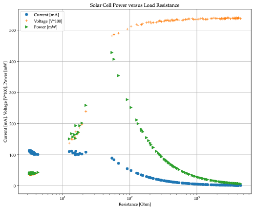
Write a Python program solar_plot.py to plot voltage, current and power versus resistance for the following values:
| Voltage | Current |
|---|---|
30mV |
100mA |
100mV |
99mA |
200mV |
95mA |
400mV |
91mA |
480mV |
85mA |
505mV |
50mA |
520mV |
10mA |
Plot measurements as dots only, do not connect them with (meaningless) lines. Your plot looks better if you use a logarithmic scale for the x-axis.
Submit the program to gradescope and bring a copy to the lab so you will be ready to document your measurements.
4.2. Reading
Read “How to use a breadboard”, https://learn.sparkfun.com/tutorials/how-to-use-a-breadboard. Are the power rails on opposite sides of the board electrically connected?
“Introduction to soldering”, https://learn.adafruit.com/adafruit-guide-excellent-soldering. To what temperature do you heat the solder iron for
60/40 solder |
Celsius |
Lead-free solder |
Celsius |
5. Lab
5.1. Solder
Figure 4 shows the parts needed for this lab.
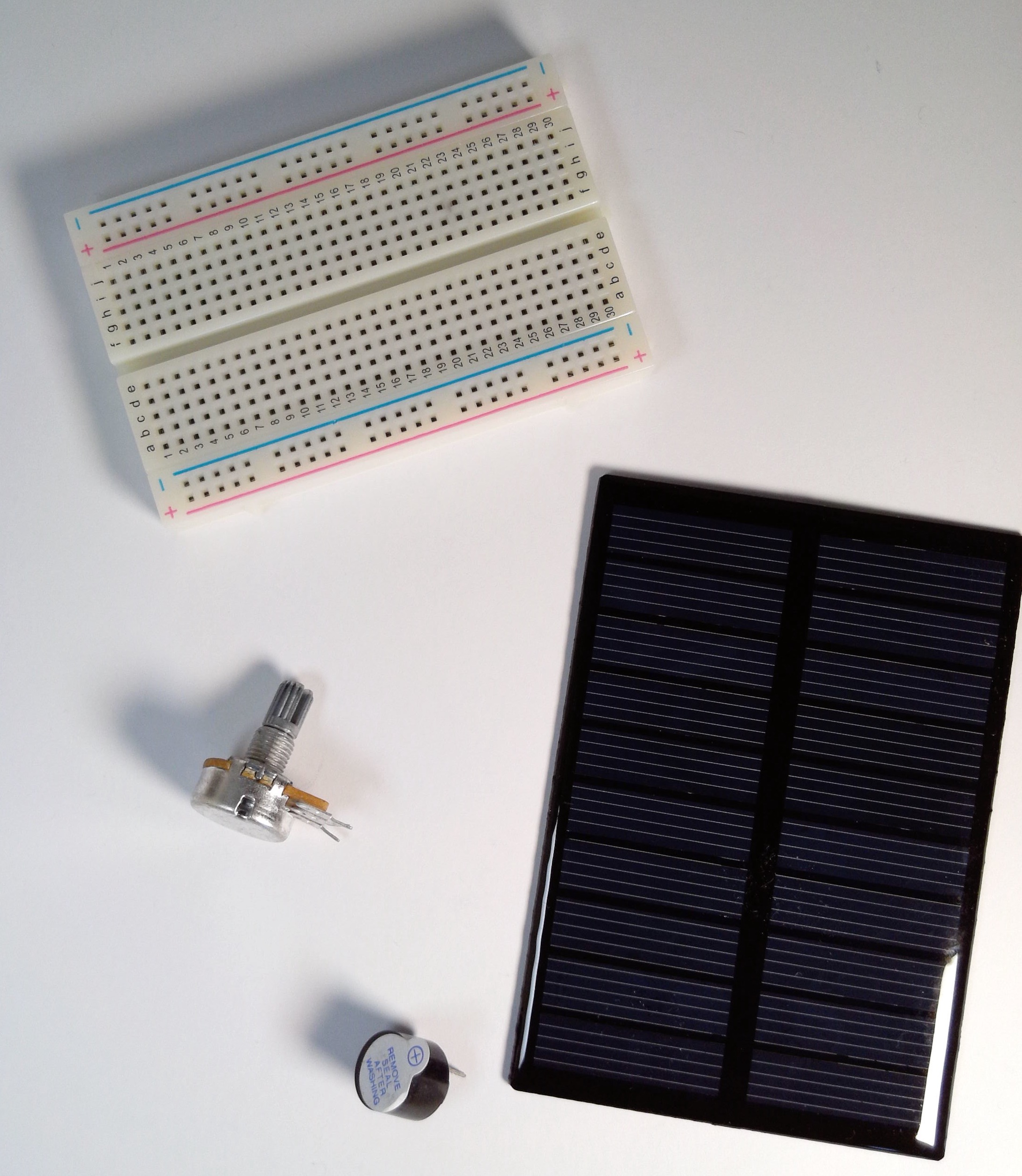
First we will solder wires to the solar cell. The instructor will demonstrate how to do this.
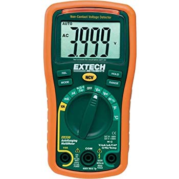
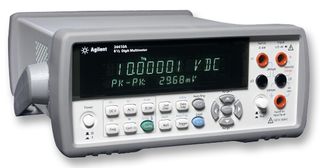
5.2. Digital Multimeter
Digital multimeter (Figure 5 or Figure 6) are used to measure voltage, current and resistance. Some instruments have additional functions such as continuity testing.
Dials or buttons are used to set the appropriate function. Some meters have separate positions to set the measurement range, e.g. Volt, mV or µA, mA, Amps. Many meters have separate connections for the test leads to measure voltage and current. Check the markings on your instrument and consult the manual or check with a instructor if you are unsure how to use the instrument.
5.3. Solar Cell Characterization
Now you are ready to characterize the solar cell. Place it in bright sunshine. You may also substitute an artificial light (Halogen works well, high efficiency LED does not) for the sun. Keep the distance between the cell and the light constant at 20 … 30cm. Putting the light closer heats up the solar cell, reducing its efficiency, resulting in inconsistent measurement results.
Record your measurements in a table (add rows as needed), or input them directly into the plotting program.
| Resistance | Voltage | Current | Power |
|---|---|---|---|
Be efficient! Remember that you want to determine the maximum power. Ideally, this takes only a single power measurement. Unless you are the oracle of Delphi, you will need several measurements. After each measurement, compute the power and decide what measurement to perform next to maximize the information you acquire to find the power maximum.
If you have only a single instrument, you will need to reconfigure your circuit between voltage, current, and resistance measurements. Consider that you can compute one from the other two. Which two measurements require the least amount of reconfiguration?
Report your results below and ask the instructor for a checkoff.
Condition for maximum power:
| Resistance | Voltage | Current | Power |
|---|---|---|---|
Plot of voltage, current, power versus log resistance (i.e. use logarithmic scale for the x-axis):