 ,
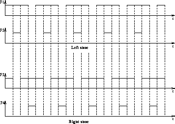
can be simulated by square-wave external forces (Figure
4).
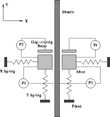
The linear electrostatic stepper motor described in section
2 is equivalent to a planar system illustrated
by figure 3, where the electrostatic gap-closing
forces  ,
can be simulated by square-wave external forces (Figure
4).

Figure 3: The abstract model of a electrostatic stepper motor.

Figure 4: The simulated electrostatic gap-closing forces.
The spring-shoe-spring structure shown in figure
3 is difficult to simulate by Impulse.
The first difficulty is due to the side motion of the spring. For
instance, when the X-spring drags a shoe along the X-direction, the
Y-spring will have a small side motion which is perpendicular to its
spring axis. The second difficulty comes from the looped forwarded
dynamics. Each spring has one end attached to the shoe and another end
fixed, therefore the spring-shoe-spring structure contains a loop:
inertia-frame  X-spring
  shoe
shoe  Y-spring
 inertia-frame. Impulse,
does not allow any loops in linked structures.
To solve this problem, we assume that the effect of the X-spring can
be neglected when the shoe is doing a Y-motion, and the effect of the
Y-spring can be neglected when the shoe is doing an X-motion. Namely
we assume that both springs are ideal linear springs. Under this
assumption, we can build the spring-shoe-spring structure as a
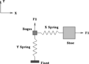
multi-body robot as shown in figure 5.
The ``bogus'' link is constrained to the inertia frame by a
prismatic joint along the Y direction. The shoe is constrained to the
``bogus'' frame by a prismatic joint along the X direction. The
square wave like force  will be applied to the ``bogus'' link,
and
  to the shoe. This model is dynamically equivalent to
abstract model shown in figure 3, under the
ideal linear spring assumption.

Figure 5: The Simulation model for the left shoe.
The physical linear eletrostatic stepper motor rests on a supporting surface, with supporting beams attached to each piece. However all motions are planar motions in the X-Y plane. If we build such a supporting surface in the simulation model, much computation will be wasted by checking the collisions between the shuttle (or shoes) and the supporting surface, which does not contribute to the behavior of the stepper motor at all. Therefore to avoid the unnecessary collision detection, we build the shuttle as an robot with only one degree of freedom: constrained to the inertia frame with a prismatic joint.
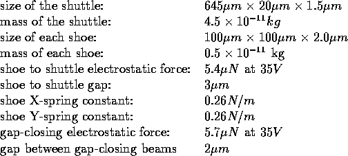
The physical parameters of the MEMS stepper motor are too small to simulate directly using Impulse. The true parameters from [8] are as following:

The above small values cause numerical instability due to the floating
point integration. In order to scale them to the reasonable range
Impulse,
we changed the unit of mass to nano-gram, dimension to  and
therefore the force to
  .
.