Geometry
The SLIDE
surface,
point,
and face
are special primitives that can not be directly instanced in groups.
surface
A surface statement defines the material properties of a
surface.
| SLIDE Definition |
tclinit Definition |
| surface id |
| |
color ( color_triple )
reflectivity ( reflectivity_triple )
exponent exponent_float
metallic metallic_float
bitmap "texture_filename" SLF_TEXMAP
ribbegin "rib_string"
ribend "rib_string"
|
| endsurface |
|
slide create surface id \
|
| |
-color { color_triple } \
-reflectivity { reflectivity_triple } \
-exponent exponent_float \
-metallic metallic_float \
-bitmap "texture_filename" SLF_TEXMAP \
-ribbegin "rib_string" \
-ribend "rib_string" \
|
|
| SLIDE Defaults |
tclinit Defaults |
| surface id |
| |
color ( 0.5 0.5 0.5 )
reflectivity ( 1.0 1.0 1.0 )
exponent 1.0
metallic 0.0
bitmap SLF_NULL SLF_TEXMAP
ribbegin SLF_NULL
ribend SLF_NULL
|
| endsurface |
|
| slide create surface id \ |
| |
-color { 0.5 0.5 0.5 } \
-reflectivity { 1.0 1.0 0.0 } \
-exponent 1.0 \
-metallic 0.0 \
-bitmap $SLF_NULL SLF_TEXMAP
-ribbegin $SLF_NULL \
-ribend $SLF_NULL
|
|
| Field |
Description |
| color |
The diffuse color of the surface as an RGB triple, where the
red, green and blue components are each in the range [0, 1]. |
| reflectivity
| The coefficients of reflectivity for ambient, diffuse, and
specular reflection in that order. These three coefficients are in
the range [0, 1]. |
| exponent
| The exponent in the Phong lighting term. This is portional
to the shininess of the surface which is inversely proportional to the
surface roughness. |
| metallic
| The metallic factor of the surface, and is used to calculate
the specular color of the surface from its diffuse color and the color
of the illuminating light. This value is in the range [0, 1]. |
| bitmap file.gif SLF_TEXMAP
| The name of a GIF image file that will be used as a texture
map for the surface. The image should have dimensions that are powers
of 2 (2n x 2m) in order to be
displayed properly. Any image that is not of the proper dimensions
will be cropped. |
A more detailed explanation of these values and their role in
doing lighting calculations is provided in the Lighting Model section.
Examples:
| Red Matte Surface |
| Static SLIDE |
Procedural SLIDE |
# Red Matte Surface

surface sRed
  color        (1 0 0)
  reflectivity (0.95 0.95 0)
endsurface
|
# Red Matte Surface
tclinit {
  slide create surface sRed \
    -color        { 1 0 0 } \
    -reflectivity { 0.95 0.95 0 }
}
|
defines a fully saturated matte red material that reflects most
light diffusely and none specularly.
| Shiny Metallic Violet Surface |
| Static SLIDE |
Procedural SLIDE |
# Shiny Metallic Violet Surface

surface sShinyViolet
  color        (0.8 0.3 1.0)
  reflectivity (0.1 0.1 0.9)
  exponent     2.0
  metallic     0.8
endsurface
|
# Shiny Metallic Violet Surface
tclinit {
  slide create surface sShinyViolet
    -color        {0.8 0.3 1.0}
    -reflectivity {0.1 0.1 0.9}
    -exponent     2.0
    -metallic     0.8
}
|
defines a metallic violet material that reflects some light
diffusely and yields strong specular highlights.
Inheritance of Surface Properties
Surface properties are propogated down the scene hierarchy in the
same manner as shading flags. A node in the scene hierarchy will pass
down its local surface object unless that surface is SLF_INHERIT in
which case it will pass along its parent's surface object. There is
no mechanism that allows a parent node to override a descendant's
locally defined surface property. The default surface object for a
node is SLF_INHERIT.
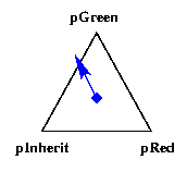
The propogation of surface properties is further complicated by
interactions with
shading flags
down at the
face
and
point
levels. The following example illustrates the difference in surface
property inheritance between flat and Gouraud shading. The example
contains a single triangle with a blue surface applied to it. Two of
the points which define the triangle have their own red and green
surface properties assigned to them while the third one has
SLF_INHERIT which means that it will inherit the blue
surface property from the triangular face.
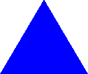
With flat shading applied, the face ignores any surface properties
defined on its points and uses the surface property of the face to do
shading. The entire triangle will be a single color under flat
shading. If lighting is disabled, the triangle will simply take on
the color value of the surface. If lighting is enabled, one lighting
calculation will be done for the triangle at its psuedo-centroid (the
unweighted average of the positions of all of the vertices of the
face) using the face normal and the color value from the face's
surface property.
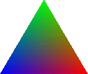
With Gouraud shading applied, every vertex of the face can have a
separate surface property, although only a single texture map will be
used per face. If a point has a surface property locally defined then
it will use that surface. If the point uses the default
SLF_INHERIT surface then it will inherit the surface
property of the face. In the example, the first two points use their
red and green surfaces, respectively, while the third point inherits
the blue surface from the face. If lighting is disabled like in the
image below, the color values assigned at the different vertices will
be linearly interpolated across the area of the face. With lighting
enabled, a separate lighting calculation will be preformed at each
vertex using the point's location, surface property, and normal. Then
the calculated color values will be linearly interpolated across the
area of the face.
surface sRed
  color ( 1 0 0 )
endsurface
surface sGreen
  color ( 0 1 0 )
endsurface
surface sBlue
  color ( 0 0 1 )
endsurface

point pRed ( 1 0 0 )
  surface sRed
endpoint
point pGreen ( 0 1.7 0 )
  surface sGreen
endpoint
point pInherit ( -1 0 0 )
  surface SLF_INHERIT
endpoint

face fTriangle ( pRed pGreen pInherit )
  surface sBlue
endface

object oFlat ( fTriangle )
  shading SLF_FLAT
endobject
object oGouraud ( fTriangle )
  shading SLF_GOURAUD
endobject
|
|
point
A point statement defines a point in 3D space which can be
reference by its id in a
face
to define the face's geometry.
| SLIDE Definition |
tclinit Definition |
|
|
| SLIDE Defaults |
tclinit Defaults |
| point id
( point_triple )
|
| |
normal [computed from adjacent face normals]
texture ( 0.0 0.0 )
surface $SLF_INHERIT
ribbegin SLF_NULL
ribend SLF_NULL
|
| endpoint |
|
| slide create point
id { point_triple } \
|
| |
-normal [computed from adjacent face normals] \
-texture { 0.0 0.0 } \
-surface $SLF_INHERIT \
-ribbegin $SLF_NULL \
-ribend $SLF_NULL
|
|
| Field |
Description |
| position |
The point_triple defines the 3D position of the point. |
| normal |
A unit length 3D vector attached to a point to define the
surface normal at the point. This combined with Gouraud shading is
useful for approximating smooth, curved surfaces using a polygonal
model. If a point normal is not explicitly defined then the point
will be assigned a normal which is the weighted average of the face
normals incident apon the point. The weighting factor used for each
face normal is the angle between the two adjacent edges within the
face. |
| texture |
A (u, v, w) triple of texture coordinates. These
values are in texture space and define how to map the texture onto the
geometry of the object. Currently only the u and v
coordinates are being used in conjunction with normal surface texture
mapping. The texture maps are rectangular and their domain is defined
to be (u, v) = ( [0, 1], [0, 1] ). Values outside this range
will cause the texture to be repeatedly wrapped along the surface. In
the future, 3D solid texture maybe supported at which time the
w coordinate will be utilized. |
Example:
| Red Point |
| Static SLIDE |
Procedural SLIDE |
point p1 ( 0 0 2.5 )
  surface sRed
endpoint
|
tclinit {
  slide create point p1 { 0 0 2.5 } \
    -surface sRed
}
|
defines a point named p1 which lies 2.5 units from the
origin along the z-axis and has a vertex color defined by the
surface sRed.
face
The face statement describes a planar convex polygon. The
polygon of the face is defined by a list of
point
identifiers which enumerate the vertices of the face in
counterclockwise order around the face contour.
| SLIDE Definition |
tclinit Definition |
|
|
| SLIDE Defaults |
tclinit Defaults |
| faceid
( point_idlist )
|
| |
surface SLF_INHERIT
ribbegin SLF_NULL
ribend SLF_NULL
|
| endface |
|
| slide create face id
{ point_idlist } \
|
| |
-surface $SLF_INHERIT \
-ribbegin $SLF_NULL \
-ribend $SLF_NULL
|
|
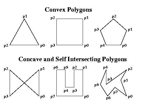
The face is defined for planar convex polygons. The
behavior for non-planar, concave, and self intersecting polygon
descriptions is undefined.
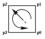
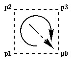
A face has a front side and a back side which is important
to the description of closed polyhedrons. The normal to a face points
out of the face on the front side of the face. The ordering of the
vertices around the contour of the face defines its orientation. This
orientation is based on the right-hand rule for cross products. A
counterclockwise ordering of vertices around the contour implies a
normal which is pointing outward, so this is the front side of the
polygon. A clockwise ordering of vertices around the contour implies
a normal which is pointing inward, so this is the back side of the
polygon.
Front Facing Polygon
Counterclockwise
Vertex Ordering |
# Front Facing Square
point p0 ( 1 0 0 ) endpoint
point p1 ( 1 1 0 ) endpoint
point p2 ( 0 1 0 ) endpoint
point p3 ( 0 0 0 ) endpoint

face fFront ( p0 p1 p2 p3 )
endface
|
 |
Back Facing Polygon
Clockwise
Vertex Ordering |
# Back Facing Square
point p0 ( 1 0 0 ) endpoint
point p1 ( 0 0 0 ) endpoint
point p2 ( 0 1 0 ) endpoint
point p3 ( 1 1 0 ) endpoint

face fBack ( p0 p1 p2 p3 )
endface
|
 |
Example:
| Red Square Face |
| Static SLIDE |
Procedural SLIDE |
# Square

point p0 ( 1 0 0 ) endpoint
point p1 ( 1 1 0 ) endpoint
point p2 ( 0 1 0 ) endpoint
point p3 ( 0 0 0 ) endpoint

face fSquare ( p0 p1 p2 p3 )
  surface sRed
endface
|
# Square
tclinit {
  slide create point p0 { 1 0 0 }
  slide create point p1 { 1 1 0 }
  slide create point p2 { 0 1 0 }
  slide create point p3 { 0 0 0 }

  slide create face fSquare { p0 p1 p2 p3 } \
    -surface sRed
}
|
defines a unit square face in the first quadrant named
fSquare. The face has been assign a red surface
material.
