|
University of California, Berkeley EECS Dept, CS Division |
||
| Jordan Smith |
SLIDE: Scene Language for Interactive Dynamic Environments |
Prof. Carlo H. Séquin |
| Home | Goals | Publications | People | Gallery | Assignments | Distributions |
The following is a diagram of the SLIDE C++ class hierarchy. Subclasses point up to their superclasses. Every textual SLIDE language element has a corresponding C++ class which represents its type in the run time viewer program. Notice that most SLIDE types are directly or indirectly a subclass of CSLIDEPrimitive.
Notice that CSLIDEObject, CSLIDEGroup, and CSLIDEInstance all share a common superclass, CSLIDENode. This common CSLIDENode type eases the management of the scene graph DAG.
Notice that CSLIDERotate, CSLIDEScale, and CSLIDETranslate all share a common superclass, CSLIDETransform. This common CSLIDETransform type eases the management of transforms in the CSLIDEInstance class.

The classes which appear in red have had portions of their implementations removed. You need to complete the functionality of these classes.
The perspective warp matrix transformation and its inverse have been ripped out, and must be filled in.
You will only be using the full (Xmin Ymin Zmin) (Xmax Ymax Zmax) to do full perspective projections including oblique view frustums. The camera must compute the mGproj_vrc matrix. It should continue to be able to do parallel projections as well.
The CBound class is where a lot of your work will be done in this assignment. It is responsible for bounding box culling with its Intersect method. It is also responsible for polygon clipping. Now these must be done in 4D on homogeneous points.
For more information and diagrams checkout the SLIDE Rendering Pipeline Page. Note: Ignore the rendering pass described there and follow the one described at the bottom of this page instead.
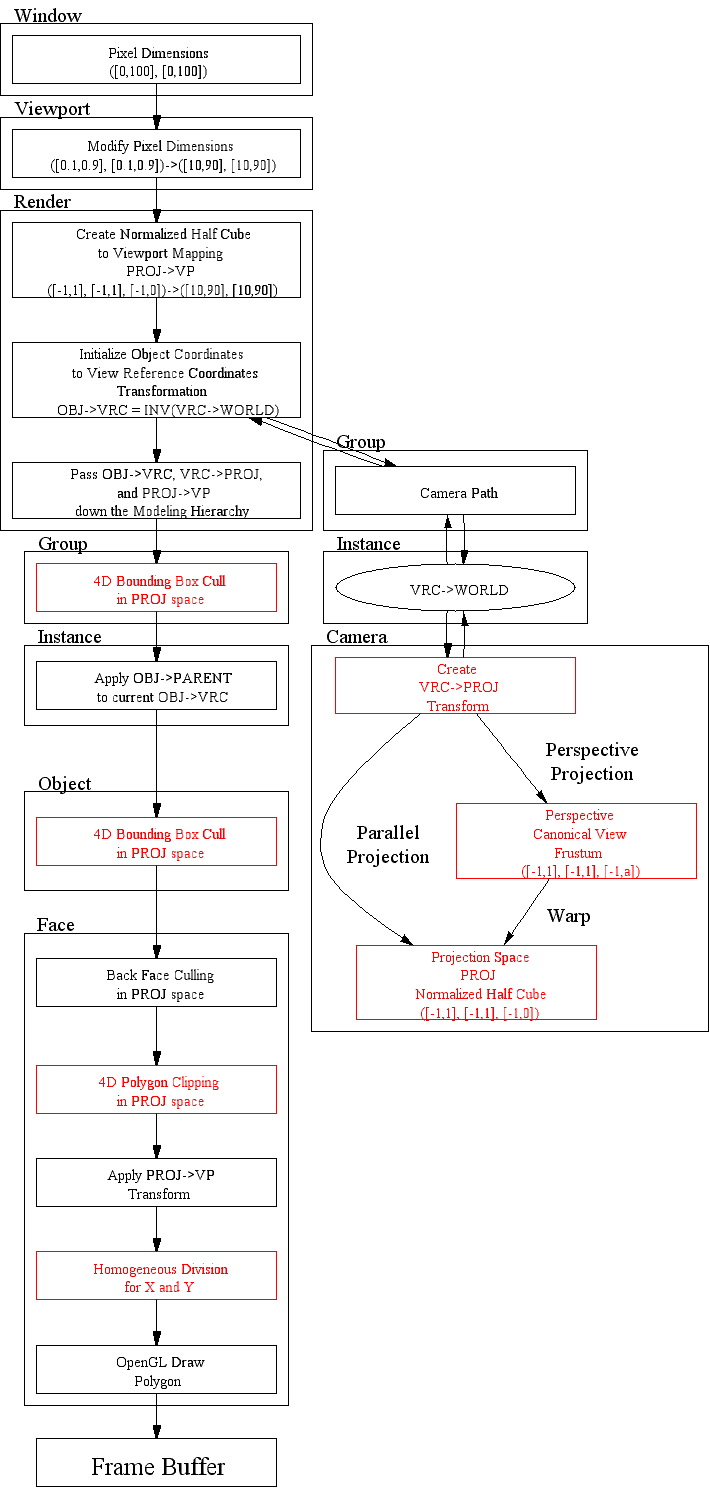
The following graph shows what should be happening for a single face in the rendering process, starting with the HandleDisplay callback on the CWindow object. Note that the matrix notation used in the diagram is ROW VECTOR form, and you will be coding COLUMN VECTORS in the project. The red blocks indicate which portions of the rendering pipeline have changed since the last assignment. These are the ones which you will be creating.

You can also download the postscript version of this graph: render.ps
This page was originally built by Jordan Smith.
Last modified: Sunday, 07-Mar-1999 16:20:13 PST