Syntax for Previous Version
Spline Nodes
The spline nodes are spline curves and surface patches. They also include the sweep and sweepmorph primitives which use crosssections.
controlpoint
| SLIDE Definition |
tclinit Definition |
| controlpoint id
|
| |
point point_id
scale ( x_float y_float z_float )
rotate ( x_float y_float z_float )
crosssection crosssection_id
ribbegin "rib_string"
ribend "rib_string"
|
| endpoint |
|
| slide create controlpoint |
| |
id \
-point point_id \
-scale { x_float y_float z_float } \
-rotate { x_float y_float z_float } \
-crosssection crosssection_id \
-ribbegin "rib_string" \
-ribend "rib_string" \
|
|
| SLIDE Defaults |
|---|
| controlpoint id
|
| |
point no default id
scale (1.0 1.0 1.0)
rotate (0.0 0.0 0.0)
crosssection none
ribbegin SLF_NULL
ribend SLF_NULL
|
| endcontrolpoint |
|
A controlpoint is a special type of point
that can be used in a
bsplinecurve,
beziercurve, and
polyline.
A controlpoint should only be used for the path of a
sweep
or
sweepmorph.
A controlpoint not only allows you to specify a control position, but
also a control crosssection and control scale and rotation for warping how
a
crosssection
is swept over a path.
| Field |
Description |
| point |
Reference to a point.
|
| scale |
Scale in x, y, and z of a sweep's crosssection.
|
| rotate |
Rotation around the x, y, and z axis of a sweep's crosssection.
|
| crosssection |
Reference to a crosssection.
|
Example:
bsplinecurve
| SLIDE Definition |
tclinit Definition |
|
|
| slide create bsplinecurve id \
|
| |
-drawcontrols drawcontrols_bool \
-order order_float \
-knotlist float \
-controlpointlist controlpoint_idlist \
-closed closed_int \
-slices slices_int \
-surface surface_id \
-shading shading_flag \
-lod lod_flag \
-ribbegin "rib_string" \
-ribend "rib_string" \
|
|
| SLIDE Defaults |
|---|
| bsplinecurve id
|
| |
drawcontrols 0
order 4.0
knotlist (0 1 2 3 4 5 6 7)
controlpointlist Note: these are the locations
of the default control points;
there are no corresponding slide points.
((-1.5 0.0 0.0) (-0.5 1.0 0.0) (0.5 1.0 0.0) (1.5 0.0 0.0))
closed 0
slices 5
surface SLF_INHERIT
shading SLF_INHERIT
lod SLF_FULL
ribbegin SLF_NULL
ribend SLF_NULL
|
| endbsplinecurve |
|
A bsplinecurve statement describes a curve that approximates the
points
or
controlpoints
defined by the controlpoint_idlist.
A bsplinecurve can be used as a
sweep path,
sweepmorph path, or
crosssection.
The dynamic values are: closed_bool, slices_int, and the points in the controlpoint_idlist.
The bsplinecurve parameters have the following constraints:
order >= 3
#knots >= 2*order
slices <= 1000
order + #control points = #knots
| Field |
Description |
| order |
The order of the BSpline curve.
3 <= order <= #controlpoints
|
| knotlist |
The BSpline knot values. If the knotlist is
not specified then the default values are
( 0 1 2 ... #knots-1)
#knots >= 2*order
order + #controlpoints = #knots
|
| controlpointlist |
A list containing points or controlpoints.
3 <= #controlpoints
|
| closed |
Specifies whether the curve is closed or not.
0 = closed
|
| slices |
The integer number of segments to draw the curve with.
0 < zslices <= 1000
|
| drawcontrols |
Boolean that specifies whether or not to draw the control structure.
|
Example:
point p1 (-1 -1 0) endpoint
point p2 (-2 0 0) endpoint
point p3 (-1 1 0) endpoint
point p4 ( 0 0 0) endpoint
point p5 ( 1 -1 0) endpoint
point p6 ( 2 0 0) endpoint
point p7 ( 1 1 0) endpoint
controlpoint cp1 point p1 endcontrolpoint
controlpoint cp5 point p5 endcontrolpoint
|
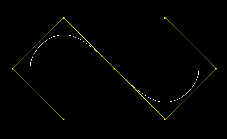
B-spline curve with yellow control polygon
|
bsplinecurve id
|
| |
order 4
controlpointlist (cp1 p2 p3 p4 cp5 p6 p7)
slices 30
drawcontrols 1
|
| endbsplinecurve |
|
beziercurve
| SLIDE Definition |
tclinit Definition |
|
|
|
| SLIDE Defaults |
|---|
| beziercurve id
|
| |
drawcontrols 0
controlpointlist Note: these are the locations
of the default control points;
there are no corresponding slide points.
((-1.5 0.0 0.0) (-0.5 1.0 0.0) (0.5 1.0 0.0) (1.5 0.0 0.0))
slices 5
surface SLF_INHERIT
shading SLF_INHERIT
lod SLF_FULL
ribbegin SLF_NULL
ribend SLF_NULL
|
| endbeziercurve |
|
A beziercurve statement describes a surface that interpolates the
end points and approximates the other points defined by the controlpoint_idlist (which contains either
points
or
controlpoints).
A beziercurve can be used as a
sweep path,
sweepmorph path, or
crosssection.
The dynamic values are: slices_int and the points in the controlpoint_idlist.
The beziercurve parameters have the following constraints:
#control points >= 3
slices <= 100
order = #control points
| Field |
Description |
| controlpointlist |
A list containing points or controlpoints. The length of this list must
be atleast 3.
|
| slices |
The integer number of segments to draw the curve with.
0 < zslices <= 1000
|
| drawcontrols |
Boolean that specifies whether or not to draw the control structure.
|
Example:
point p1 (-1.5 -0.5 0) endpoint
point p2 (-0.5 0.5 0) endpoint
point p3 ( 0.5 0.5 0) endpoint
point p4 ( 1.5 -0.5 0) endpoint
controlpoint cp3 point p3 endcontrolpoint
|
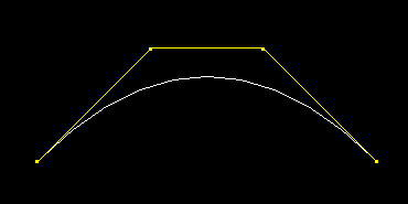
Bezier curve with yellow control polygon |
beziercurve id
|
| |
controlpointlist (p1 p2 cp3 p4)
drawcontrols1
|
| endbeziercurve
|
|
polyline
| SLIDE Definition |
tclinit Definition |
|
|
|
| SLIDE Defaults |
|---|
| polyline id
|
| |
drawpoints 0
pointlist Note: these are the locations
of the default points;
there are no corresponding slide points.
((-2.0 -1.0 0.0) (-2.0 1.0 0.0) (0.0 1.0 0.0)
(0.0 -1.0 0.0) (2.0 -1.0 0.0) (2.0 1.0 0.0))
surface SLF_INHERIT
shading SLF_INHERIT
lod SLF_FULL
ribbegin SLF_NULL
ribend SLF_NULL
|
| endpolyline |
|
A polyline statement describes 3D piecewise linear segments. There must be atleast 2 points in the pointlist
(which contains either
points
or
controlpoints).
A polyline can be used as a
sweep path,
sweepmorph path, or
crosssection.
| Field |
Description |
| pointlist |
A list containing points or controlpoints. The length of this list must
be atleast 2.
|
| drawpoints |
Boolean that specifies whether or not to draw the points.
|
Example:
point p1 (-2.0 -2.0 0.0) endpoint
point p2 ( 1.0 1.0 0.0) endpoint
point p3 ( 2.0 -1.0 0.0) endpoint
point p4 ( 0.0 -1.0 0.0) endpoint
point p5 ( 3.0 1.0 0.0) endpoint
controlpoint cp1 point p1 endcontrolpoint
|
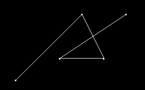
line segments with points drawn
|
polyline id
|
| |
pointlist (cp1 p2 p3 p4 p5)
drawpoints 1
|
| endpolyline
|
|
crosssection
| SLIDE Definition |
tclinit Definition |
| crosssection id
|
| |
type type_string [id]
surface surface_id
crossection_type_parameters
|
| endcrosssection |
|
| slide create crosssection id \
|
| |
-type crossection_type [id] \
-surface surface_id \
crossection_type_parameters \
|
|
| SLIDE Defaults |
tclinit Defaults |
|---|
| crosssection id
|
| |
type circle
radius 1.0
slices 5
surface SLF_INHERIT
|
| endcrosssection |
|
| slide create crosssection id \ |
| |
-type circle \
-radius 1.0 \
-slices 5 \
-surface $SLF_INHERIT \
|
|
A crosssection is a polyline, usually 2D and defined in the xy-plane,
but can be three dimensional.
A crosssection can be used by itself or in conjunction with a
sweep
or
sweepmorph.
There are 6 crosssection types:
crosssection id
type polyline id
endcrosssection
|
|
Reference to a polyline.
|
crosssection id
type beziercurve id
endcrosssection
|
|
Reference to a beziercurve.
|
crosssection id
type bsplinecurve id
endcrosssection
|
|
Reference to a bsplinecurve.
|
crosssection id
type circle
radius radius_float
slices slices_int
endcrosssection
|
|
A circle with slices_int sides.
radius > 0
slices >= 3
|
crosssection id
type cresent
radius radius_float
theta theta_float
thickness thickness_float
slices slices_int
endcrosssection
|
|
A "C" shape with an arc determined by theta and the radius.
radius > 0
theta > 0
thickness > 0
slices >= 1
|
crosssection id
type star
innerradius innerradius_float
outerradius outerradius_float
slices slices_int
endcrosssection
|
|
A star with slices_int points.
innerradius > 0
outerradius > 0
slices >= 2
|
Example:
crosssection id
|
| |
type cresent
radius 1.0
theta 70
thickness 0.2
slices 10
|
| endcrosssection |
|
|
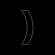
|
sweep
| SLIDE Definition |
tclinit Definition |
| sweep id
|
| |
path id
minimizetorsion minimizetorsion_bool
closed closed_bool
symmetry symmetry_int
azimuth azimuth_float
twist twist_float
endpath
crosssection id
orientation orienation_bool
begincap begincap_bool
endcap endcap_bool
surface surface_id
texture ( texture_triple ) [( texture_triple )]
( texture_triple ) [( texture_triple )]
transform
transform_statement
endtransform
endcrosssection
...
...
meshtype mesh_flag
drawsweep drawsweep_bool
drawpath drawpath_bool
solid solid_flag
surface surface_id
shading shading_flag
lod lod_flag
ribbegin "rib_string"
ribend "rib_string"
|
| endsweep |
|
| slide create sweep id \
|
| |
-path id \
-minimizetorsion minimizetorsion_bool \
-closed closed_bool \
-symmetry symmetry_int \
-azimuth azimuth_float \
-twist twist_float \
-crosssection id \
-orientation orientation_bool \
-begincap begincap_bool \
-endcap endcap_bool \
-surface surface_id \
-texture { texture_triple } [{ texture_triple }] { texture_triple } [{ texture_triple }] \
-transform { { transform_statement } \
{ transform_statement } \
... \
... \
... \
-meshtype mesh_flag
-drawsweep drawsweep_bool \
-drawpath drawpath_bool \
-solid solid_flag \
-surface surface_id \
-shading shading_flag \
-lod lod_flag \
-ribbegin "rib_string" \
-ribend "rib_string" \
|
|
| SLIDE Defaults |
tclinit Defaults |
|---|
| sweep id
|
| |
path id
minimizeTorsion 0
closed 0
symmetry 1
azimuth 0.0
twist 0.0
endpath
crosssection no_default_id
orientaion 0
begincap 0
endcap 0
endcrosssection
meshtype SLF_TRIANGLES
drawsweep 1
drawpath 0
solid SLF_SOLID
surface SLF_INHERIT
shading SLF_INHERIT
lod SLF_FULL
ribbegin SLF_NULL
ribend SLF_NULL
|
| endsweep |
|
| slide create sweep id \ |
| |
-path id \
-minimizeTorsion 0 \
-closed 0 \
-symmetry 1 \
-azimuth 0.0 \
-twist 0.0 \
1.0 1.0 0.0 ...} \
-crosssection no_default_id \
-orientaion 0 \
-begincap 0 \
-endcap 0 \
-meshtype $SLF_TRIANGLES \
-drawsweep 1 \
-drawpath 0 \
-solid $SLF_SOLID \
-surface $SLF_INHERIT \
-shading $SLF_INHERIT \
-lod $SLF_FULL \
-ribbegin $SLF_NULL \
-ribend $SLF_NULL
|
|
A sweep statement describes the result of sweeping the
crosssections
along the path. The path must a
bsplinecurve,
beziercurve, or
polyline.
Each path has a set of Frenet Frames (tangents, normals, & binormals) that are
used to determine how the cross section will twist along the path.
The user can control the twist in five ways and these options are additive in the order given below:
1) minimizetorsion - minimizes the twisting of the intrinsic Frenet frame.
2) closed - specifies that the path is closed.
This changes the Frenet frames so that the first and last Frenet
frames are aligned using the symmetry of the crosssection.
For example, a square has symmetry 4, so when a path is
closed the Frenet Frames should be aligned within
(360/4)=90 degrees about the tangent.
3) azimuth - angle about the tangent that all Frenet frames will be rotated by.
4) twist - angle about the tangent that specifies the overall amount of twist from the first Frenet frame to the last.
5) warp - sets each scale and twist angle explicitly:
In the path
controlpoints
the scale and rotate values transform the
crosssection
in the Frenet Frame coordinate system. (x y z) correspond to
the Frenet Frame (normal, binormal, tangent), which are drawn in
(red, green, blue).
| Field |
Description |
| orientation |
The orientation of the swept crosssection.
0 = outward; 1 = inward
|
| begincap |
Boolean that specifies whether or not to draw a cap at the
beginning of the swept crosssection.
|
| endcap |
Boolean that specifies whether or not to draw a cap at the
end of the swept crosssection.
|
| transform |
List of transforms to apply to the crosssection before it is swept.
|
Example:
crosssection csCircle
|
| |
type circle
radius 0.25
slices 20
|
endcrosssection
|
crosssection csStar
|
| |
type star
outerradius 0.70
innerradius 0.35
slices 5
surface sBlue
|
endcrosssection
|
|
point p1 ( -4.0 4.0 0.0) endpoint
point p2 ( 4.0 4.0 0.0) endpoint
point p3 ( 4.0 -4.0 0.0) endpoint
point p4 ( -4.0 -4.0 0.0) endpoint
|
beziercurve bz
|
| |
controlpointlist (p1 p2 p3 p4)
drawcontrols 1
|
| endbeziercurve
|
|
sweep sw
|
| |
path bz
minimizetorsion 1
endpath
crosssection csCircle
surface sRed
endcrosssection
crosssection csStar
transform
translate (1.2 0 0)
endtransform
endcrosssection
meshtype SLF_TRIANGLES
drawsweep 1
drawpath 0
|
| endsweep |
|
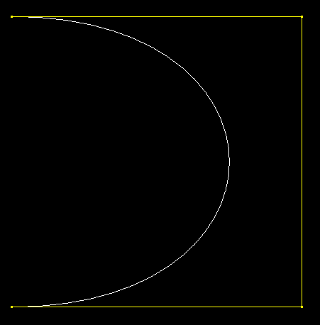
Bezier curve path of the sweep
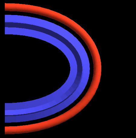
Final swept circle and star
|
sweepmorph
| SLIDE Definition |
tclinit Definition |
| sweepmorph id
|
| |
path id
minimizeTorsion minimizeTorsion_bool
closed closed_bool
symmetry symmetry_int
azimuth azimuth_float
twist twist_float
endpath
begincap begincap_bool
endcap endcap_bool
meshtype mesh_flag
drawsweep drawsweep_bool
drawpath drawpath_bool
texture ( texture_triple ) [( texture_triple )] ( texture_triple ) [( texture_triple )]
solid solid_flag
surface surface_id
shading shading_flag
lod lod_flag
ribbegin "rib_string"
ribend "rib_string"
|
| endsweepmorph |
|
| slide create sweepmorph id \
|
| |
-path id \
-minimizeTorsion minimizeTorsion_bool \
-closed closed_bool \
-symmetry symmetry_int \
-azimuth azimuth_float \
-twist twist_float \
-begincap begincap_bool \
-endcap endcap_bool \
-meshtype mesh_flag
-drawsweep drawsweep_bool \
-drawpath drawpath_bool \
-texture { texture_triple } [{ texture_triple }] { texture_triple } [{ texture_triple }] \
-solid solid_flag \
-surface surface_id \
-shading shading_flag \
-lod lod_flag \
-ribbegin "rib_string" \
-ribend "rib_string" \
|
|
| SLIDE Defaults |
tclinit Defaults |
|---|
| sweepmorph id
|
| |
path id
minimizeTorsion 0
closed 0
symmetry 1
azimuth 0.0
twist 0.0
endpath
begincap 0
endcap 0
meshtype SLF_TRIANGLES
drawsweep 1
drawpath 0
texture ( 0.0 0.0 ) [( 1.0 0.0 )] ( 1.0 1.0 ) [( 0.0 1.0 )]
solid SLF_SOLID
surface SLF_INHERIT
shading SLF_INHERIT
lod SLF_FULL
ribbegin SLF_NULL
ribend SLF_NULL
|
| endsweepmorph |
|
| slide create sweepmorph id \ |
| |
-path id \
-minimizeTorsion 0 \
-closed 0 \
-symmetry 1 \
-azimuth 0.0 \
-twist 0.0 \
-begincap 0 \
-endcap 0 \
-meshtype $SLF_TRIANGLES \
-drawsweep 1 \
-drawpath 0 \
-texture { 0.0 0.0 } [{ 1.0 0.0 }] { 1.0 1.0 } [{ 0.0 1.0 }] \
-solid $SLF_SOLID \
-surface $SLF_INHERIT \
-shading $SLF_INHERIT \
-lod $SLF_FULL \
-ribbegin $SLF_NULL \
-ribend $SLF_NULL
|
|
A sweepmorph is very similar to a
sweep.
However, instead of specifying crosssections inside the sweepmorph,
crosssections are associated with the path
controlpoints. Any path controlpoint may have a crosssection reference, but
the first and last controlpoint must contain a crosssection reference.
The crosssections are linearly interpolated across the path.
All crosssections must have the same number of points.
Example:
crosssection cCircle
|
| |
type circle
radius 0.6
slices 22
|
endcrosssection
|
crosssection cStar
|
| |
type star
outerradius 1.0
innerradius 0.75
slices 11
|
endcrosssection
|
|
point p1 (-3.0 0.0 0.0) endpoint
point p2 (-1.0 2.0 0.0) endpoint
point p3 ( 1.0 2.0 0.0) endpoint
point p4 ( 3.0 0.0 1.0) endpoint
|
controlpoint cp1
|
| |
point p1
crosssection cCircle
|
endcontrolpoint
|
controlpoint cp4
|
| |
point p4
crosssection cStar
|
endcontrolpoint
|
beziercurve bz
|
| |
controlpointlist (cp1 p2 p3 cp4)
slices 30
drawcontrols 1
|
| endbeziercurve
|
|
sweepmorph sm
|
| |
path bz
minimizetorsion 1
endpath
begincap 1
endcap 1
drawsweep 1
|
| endsweep |
|
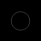

2D crosssections cCircle and cStar
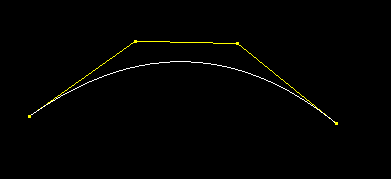
The beziercurve path for the sweepmorph
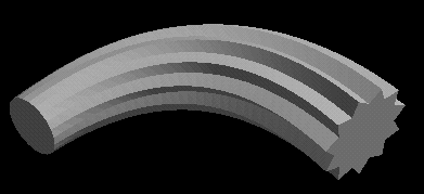
The sweepmorph with endcaps
|
bsplinepatch
| SLIDE Definition |
tclinit Definition |
bsplinepatch id
|
| |
drawcontrols drawcontrols_bool
uorder uorder_float
uknots uknots_float
uknotlist float
vorder vorder_float
vknots vknots_float
vknotlist float_list
controlpointlist controlpoint_idlist
uslices uslices_int
vslices vslices_int
offset distance_float connected_bool
texture ( texture_triple ) [( texture_triple )] ( texture_triple ) [( texture_triple )]
solid solid_flag
surface surface_id
shading shading_flag
lod lod_flag
ribbegin "rib_string"
ribend "rib_string"
|
| endbsplinepatch |
|
| slide create bsplinepatch id \
|
| |
-drawcontrols drawcontrols_bool \
-uorder uorder_float \
-uknots uknots_float \
-uknotlist float \
-vorder vorder_float \
-vknots vknots_float \
-vknotlist float_list \
-controlpointlist controlpoint_idlist \
-uslices uslices_int \
-vslices vslices_int \
-offset distance_float connected_bool \
-texture { texture_triple } [{ texture_triple }] { texture_triple } [{ texture_triple }] \
-solid solid_flag \
-surface surface_id \
-shading shading_flag \
-lod lod_flag \
-ribbegin "rib_string" \
-ribend "rib_string" \
|
|
| SLIDE Defaults |
|---|
| bsplinepatch id
|
| |
drawcontrols 0
uorder 4.0
uknots 8.0
uknotlist (0 1 2 3 4 5 6 7)
vorder 4.0
vknots 8.0
vknotlist (0 1 2 3 4 5 6 7)
controlpointlist Note: these are the locations
of the default control points;
there are no corresponding slide points.
((-1.5 -1.5 -1.0) (-1.5 -0.5 0.0) (-1.5 0.5 0.0) (-1.5 1.5 -1.0)
(-0.5 -1.5 0.0) (-0.5 -0.5 1.0) (-0.5 0.5 1.0)
(-0.5 1.5 0.0)
( 0.5 -1.5 0.0) ( 0.5 -0.5 1.0) ( 0.5 0.5 1.0)
( 0.5 1.5 0.0)
( 1.5 -1.5 -1.0) ( 1.5 -0.5 0.0) ( 1.5 0.5 0.0) ( 1.5 1.5 -1.0))
uslices 5
vslices 5
offset 0 0
texture ( 0.0 0.0 ) [(
1.0
0.0
)]
(
1.0
1.0
) [(
0.0
1.0
)]
solid SLF_SOLID
surface SLF_INHERIT
shading SLF_INHERIT
lod SLF_FULL
ribbegin SLF_NULL
ribend SLF_NULL
|
| endbsplinepatch |
|
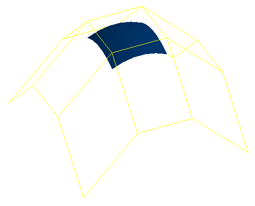 |
A bsplinepatch statement describes a surface that
approximates the control mesh defined by the
controlpoint_idlist. The surface normals point in the u
cross v direction. An offset surface is created if
distance_float is non-zero. This surface is connected to the
original surface is connected_bool is non-zero.
The bsplinepatch parameters have the following constraints:
uorder, vorder > 1
uknots >= 2*uorder
vknots >= 2*vorder
uslices, vslices <= 100
uorder + #control points in the u-direction = uknots
vorder + #control points in the v-direction = vknots
The dynamic values are: uslices, vslices, and the controlpointlist points.
Example:
point p0 (1 5 12) endpoint
...
point p19 (17 6 -2) endpoint
|
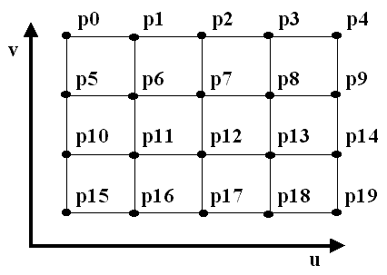
Connectivety of the control points
|
bsplinepatch id
|
| |
uorder 4
uknots 9
uknotlist (0 1 2 3 4 5 6 7 8)
vorder 4
vknots 8
vknotlist (2.3 5.1 6.3 6.4 7.2 8.9 9.2 14)
controlpointlist (p0 p1
p2 p3 p4
p5 p6 p7 p8 p9
p10 p11 p12 p13 p14
p15 p16 p17 p18 p19)
|
| endbsplinepatch |
|
bezierpatch
| SLIDE Definition |
tclinit Definition |
| bezierpatch id
|
| |
drawcontrols drawcontrols_bool
uorder uorder_float
vorder vorder_float
controlpointlist controlpoint_idlist
uslices uslices_int
vslices vslices_int
offset distance_float connected_bool
texture ( texture_triple ) [( texture_triple )] ( texture_triple ) [( texture_triple )]
solid solid_flag
surface surface_id
shading shading_flag
lod lod_flag
ribbegin "rib_string"
ribend "rib_string"
|
| endbezierpatch |
|
| slide create bezierpatch id \
|
| |
-drawcontrols drawcontrols_bool \
-uorder uorder_float \
-vorder vorder_float \
-controlpointlist controlpoint_idlist \
-uslices uslices_int \
-vslices vslices_int \
-offset distance_float connected_bool \
-texture { texture_triple } [{ texture_triple }] { texture_triple } [{ texture_triple }] \
-solid solid_flag \
-surface surface_id \
-shading shading_flag \
-lod lod_flag \
-ribbegin "rib_string" \
-ribend "rib_string" \
|
|
| SLIDE Defaults |
|---|
| bezierpatch id
|
| |
drawcontrols 0
uorder 4.0
vorder 4.0
controlpointlist Note: these are the locations
of the default control points;
there are no corresponding slide points.
((-1.5 -1.5 -1.0) (-1.5 -0.5 0.0) (-1.5 0.5 0.0) (-1.5 1.5 -1.0)
(-0.5 -1.5 0.0) (-0.5 -0.5 1.0) (-0.5 0.5 1.0)
(-0.5 1.5 0.0)
( 0.5 -1.5 0.0) ( 0.5 -0.5 1.0) ( 0.5 0.5 1.0)
( 0.5 1.5 0.0)
( 1.5 -1.5 -1.0) ( 1.5 -0.5 0.0) ( 1.5 0.5 0.0) ( 1.5 1.5 -1.0))
uslices 5
vslices 5
offset 0 0
texture ( 0.0 0.0 ) [(
1.00.0)] (1.0 1.0
) [(0.01.0)]
solid SLF_SOLID
surface SLF_INHERIT
shading SLF_INHERIT
lod SLF_FULL
ribbegin SLF_NULL
ribend SLF_NULL
|
| endbezierpatch |
|
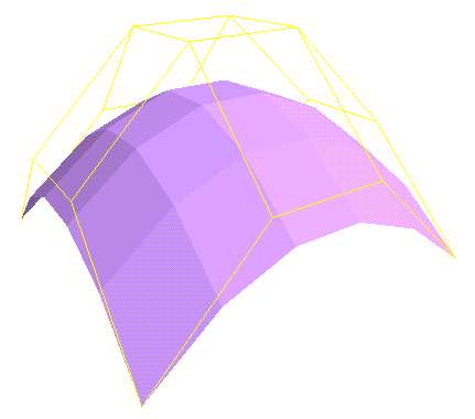 |
A bezierpatch statement describes a surface that interpolates the four
corner points of the control mesh and approximates the other points
defined by the controlpoint_idlist. The surface normals point in the
u cross v direction. An offset surface is
created if distance_float is non-zero. This surface is connected
to the original surface is connected_bool is non-zero.
The bezierpatch parameters have the following constraints:
uorder, vorder > 1
uslices, vslices <= 100
uorder = #control points in the u-direction
vorder = #control points in the v-direction
The dynamic values are: uslices, vslices, and the controlpointlist points.
Example:
point p0 (-6 4 8) endpoint
...
point p11 (2 32 -7) endpoint
|
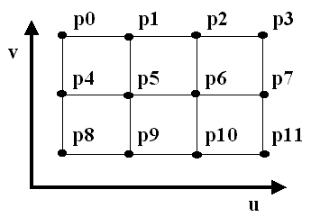
Connectivety of the control points
|
bezierpatch id
|
| |
uorder 4
vorder 3
controlpointlist (p0 p1 p2 p3
p4 p5 p6
p7
p8 p9 p10 p11)
|
| endbezierpatch |
|
nurbpatch
| SLIDE Definition |
tclinit Definition |
nurbpatch id
|
| |
drawcontrols drawcontrols_bool
uorder uorder_float
uknots uknots_float
uknotlist float
vorder vorder_float
vknots vknots_float
vknotlist float_list
controlpointlist controlpoint_idlist
uslices uslices_int
vslices vslices_int
offset distance_float connected_bool
texture ( texture_triple ) [( texture_triple )] ( texture_triple ) [( texture_triple )]
solid solid_flag
surface surface_id
shading shading_flag
lod lod_flag
ribbegin "rib_string"
ribend "rib_string"
|
| endnurbpatch |
|
| slide create nurbpatch id \
|
| |
-drawcontrols drawcontrols_bool \
-uorder uorder_float \
-uknots uknots_float \
-uknotlist float \
-vorder vorder_float \
-vknots vknots_float \
-vknotlist float_list \
-controlpointlist controlpoint_idlist \
-uslices uslices_int \
-vslices vslices_int \
-offset distance_float connected_bool \
-texture { texture_triple } [{ texture_triple }] { texture_triple } [{ texture_triple }] \
-solid solid_flag \
-surface surface_id \
-shading shading_flag \
-lod lod_flag \
-ribbegin "rib_string" \
-ribend "rib_string" \
|
|
| SLIDE Defaults |
|---|
| nurbpatch id
|
| |
drawcontrols 0
uorder 4.0
uknots 8.0
uknotlist (0 1 2 3 4 5 6 7)
vorder 4.0
vknots 8.0
vknotlist (0 1 2 3 4 5 6 7)
controlpointlist Note: these are the locations
of the default control points;
there are no corresponding slide points.
((-1.5 -1.5 -1.0) (-1.5 -0.5 0.0) (-1.5 0.5 0.0) (-1.5 1.5 -1.0)
(-0.5 -1.5 0.0) (-0.5 -0.5 1.0) (-0.5 0.5 1.0)
(-0.5 1.5 0.0)
( 0.5 -1.5 0.0) ( 0.5 -0.5 1.0) ( 0.5 0.5 1.0)
( 0.5 1.5 0.0)
( 1.5 -1.5 -1.0) ( 1.5 -0.5 0.0) ( 1.5 0.5 0.0) ( 1.5 1.5 -1.0))
uslices 5
vslices 5
offset 0 0
texture ( 0.0 0.0 ) [(
1.0
0.0
)]
(
1.0
1.0
) [(
0.0
1.0
)]
solid SLF_SOLID
surface SLF_INHERIT
shading SLF_INHERIT
lod SLF_FULL
ribbegin SLF_NULL
ribend SLF_NULL
|
| endnurbpatch |
|
A nurbpatch is rational spline surface based on
bsplinepatches
The surface normals point in the u cross v direction.
An offset surface is
created if distance_float is non-zero. This surface is connected
to the original surface is connected_bool is non-zero.
The nurbpatch parameters have the following constraints:
uorder, vorder > 1
uknots >= 2*uorder
vknots >= 2*vorder
uslices, vslices <= 100
uorder + #control points in the u-direction = uknots
vorder + #control points in the v-direction = vknots
The dynamic values are: uslices, vslices, and the controlpointlist points.
Partial Cylinder Example:
point p0 (-2 0 1.0 1.0) endpoint
point p1 (-2 0 0.0 1.0) endpoint
point p2 (-2 0 -1.0 1.0) endpoint
point p3 ({expr -2.0*0.7071} {expr 2.0*0.7071} {expr 1.0*0.7071} {expr 0.7071} ) endpoint
point p4 ({expr -2.0*0.7071} {expr 2.0*0.7071} {expr 0.0*0.7071} {expr 0.7071} ) endpoint
point p5 ({expr -2.0*0.7071} {expr 2.0*0.7071} {expr -1.0*0.7071} {expr 0.7071} ) endpoint
point p6 (0 2 1.0 1.0) endpoint
point p7 (0 2 0.0 1.0) endpoint
point p8 (0 2 -1.0 1.0) endpoint
|
nurbpatch id
|
| |
uorder 3
uknots 6
uknotlist (0 0 0 1 1 1)
vorder 3
vknots 6
vknotlist (0 0 0 1 1 1)
uslices 20
vslices 20
controlpointlist (p0 p1 p2
p3 p4 p5
p6 p7 p8)
|
| endnurbpatch |
|
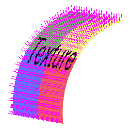
Partial cylinder with texture and normals drawn
|


