Mesh Nodes
Mesh nodes build a topologically connected mesh of polygons
represented by a Quad Edged mesh data structure. This representation
is useful for performing solid modeling operations where it is
necessary to know neighbor relationships between facets, vertices, and
edges.
mesh
A mesh statement creates a mesh facets. A mesh is
similar to an object in that it is a group of facets. The
difference is that all of the geometry of a mesh is nested
within the mesh statement and cannot be accessed by any other
entity. The mesh is able to create a Quad Edge mesh once on
start up, and then quickly update values of the mesh without having to
remesh. A mesh can contain one or more patches of facets
either closed or with boundary.
| SLIDE Definition |
tclinit Definition |
| mesh id
|
| |
vertexproperty id |
| |
|
type SLF_VERTEX_CORNER
|
| |
endvertexproperty |
| |
... |
| |
vertex id ( point_triple ) |
| |
|
normal ( normal_triple )
texture ( texture_triple )
vertexproperty vertexproperty_id
|
| |
endvertex |
| |
... |
| |
facet id
( vertex_idlist ) |
| |
endfacet |
| |
... |
| |
edgeproperty id |
| |
|
sharpness sharpness_flag
|
| |
endedgeproperty |
| |
... |
| |
edge id ( vertex_id vertex_id ) |
| |
|
edgeproperty edgeproperty_id
|
| |
endedge |
| |
... |
| |
solid solid_flag
surface surface_id
shading shading_flag
lod lod_flag
ribbegin "rib_string"
ribend "rib_string"
|
| endmesh |
|
|
| SLIDE Defaults |
tclinit Defaults |
| mesh id
|
| |
solid SLF_SOLID
surface SLF_INHERIT
shading SLF_INHERIT
lod SLF_FULL
ribbegin SLF_NULL
ribend SLF_NULL
|
| endmesh |
|
N/A |
Example: Tetrahedron
This example constructs a tetrahedral mesh with three of it edges
tagged with edge sharpnesses. Any edges that are not specifically
tagged will get a default edge sharpness of 0.0.
# Tetrahedron

mesh mTetra
  vertexproperty vpCorner
    type SLF_VERTEX_CORNER
  endvertexproperty

  vertex v1 ( 1 -1  1)
    vertexproperty vpCorner
  endvertex
  vertex v2 (-1  1  1) endvertex
  vertex v3 ( 1  1 -1) endvertex
  vertex v4 (-1 -1 -1) endvertex

  facet f1 (v2 v1 v3) endfacet
  facet f2 (v4 v3 v1) endfacet
  facet f3 (v3 v4 v2) endfacet
  facet f4 (v1 v2 v4) endfacet

  edgeproperty epSmooth
    sharpness 0.0
  endedgeproperty
  edgeproperty epSemiSharp
    sharpness 2.0
  endedgeproperty
  edgeproperty epSharp
    sharpness SLF_INFINITY
  endedgeproperty

  edge e1 (v1 v2)
    edgeproperty epSmooth
  endedge
  edge e2 (v1 v3)
    edgeproperty epSemiSharp
  endedge
  edge e3 (v1 v4)
    edgeproperty epSharp
  endedge
endmesh
|
 |
This polyhedron can then be input into a subdivision node and make full use of the different subdivision methods including sharp edge tagging.
convexhull
A convexhull statement creates a closed convex polyhedral
mesh by taking the convex hull of a cloud of 3D points. Conceptually
the process of taking a convex hull can be thought of as shrink
wrapping a set of points that are fixed in space. The convex hull is
calculated using the randomized Quickhull algorithm.
| SLIDE Definition |
tclinit Definition |
|
|
| SLIDE Defaults |
tclinit Defaults |
convexhull id
( point_idlist )
|
| |
solid SLF_SOLID
surface SLF_INHERIT
shading SLF_INHERIT
lod SLF_FULL
ribbegin SLF_NULL
ribend SLF_NULL
|
| endconvexhull |
|
| slide create convexhull id
{ point_idlist } \
|
| |
-solid $SLF_SOLID \
-surface $SLF_INHERIT \
-shading $SLF_INHERIT \
-lod $SLF_FULL \
-ribbegin $SLF_NULL \
-ribend $SLF_NULL
|
|
Example: Random Points
This example generates a set of random points in the box
( [-1,1], [-1,1], [0,1] ). It then sets them as
the input to a convexhull node which builds the convex hull
polyhedron.
tclinit {
  set iPoints 50

  set ptsRandomCloud {}
  for { set i 0 } { $i < $iPoints } { incr i } {
    set pt(X) [expr (rand() - 0.5) * 2.0]
    set pt(Y) [expr (rand() - 0.5) * 2.0]
    set pt(Z) [expr rand()]

    slide create point "pRandomCloud[subst $i]" [list $pt(X) $pt(Y) $pt(Z)]
    lappend ptsRandomCloud "pRandomCloud[subst $i]"
  }

  slide create convexhull oRandomCloud $ptsRandomCloud
}
| Solid |
Wire Frame |
 |
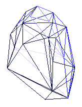 |
This polyhedron can then be input into a subdivision node,
and the resulting surface is a pleasing pebble shape.
terrain
A terrain statement creates a triangular mesh height field
from a cloud of 3D points. The triangular mesh is created by
projecting the 3D points into the XY-plane, forming the Delaunay
triangulation of the 2D points, and then restoring the Z values of the
points. With this construct it is possible to create a nonregular
mesh of triangles simply by naming the vertices without any topology
information. It is also possible to create 2D Voronoi diagrams of the
input points.
| SLIDE Definition |
tclinit Definition |
|
|
| SLIDE Defaults |
tclinit Defaults |
| terrain id
|
| |
type SLF_TERRAIN_DELAUNAY_
voronoi SLF_VORONOI_OFF
accuracy SLF_FLOAT
random SLF_OFF
drawdelaunay SLF_ON
drawvertices SLF_OFF
solid SLF_SOLID
surface SLF_INHERIT
shading SLF_INHERIT
lod SLF_FULL
ribbegin SLF_NULL
ribend SLF_NULL
|
| endterrain |
|
| slide create terrain id \
|
| |
-type SLF_TERRAIN_DELAUNAY_ \
-voronoi SLF_VORONOI_OFF \
-accuracy SLF_FLOAT \
-random SLF_OFF \
-drawdelaunay SLF_ON \
-drawvertices SLF_OFF \
-solid $SLF_SOLID \
-surface $SLF_INHERIT \
-shading $SLF_INHERIT \
-lod $SLF_FULL \
-ribbegin $SLF_NULL \
-ribend $SLF_NULL
|
|
| Field |
Description |
| type |
The Delaunay triangulation algorithm which will be used to
create the mesh, see the Delaunay type
for details.
|
| voronoi |
The algorithm which will be used to
create the Voronoi diagram, see the
Voronoi type
for details.
|
| accuracy |
The level of numeric accuracy which will be used to compute
the Delaunay triangulation and the Voronoi diagram, see the
accuray type
for details.
|
| random |
Whether or not to randomize the order of the input vertices.
This can have a great effect on the running time of some of the
algorithms.
|
| drawdelaunay |
Whether or not to draw the Delaunay triangulation mesh.
|
| drawvertices |
Whether or not to draw the input vertex sites.
|
Example: Random Terrain
This example shows how the terrain node can be used to
easily build a random terrain. The example only needs to generate a
set of random points because the connectivity information will be
implicit in the X and Y position of the points based on the Delaunay
triangulation.
tclinit {
  package require slideui

  toplevel .slfWindow.ui

  CreateSLIDETerrainObject oTerrain
  set widget [CreateSLIDETerrainUI .slfWindow.ui oTerrain]
  pack $widget
}

tclinit {
  set iPoints 20

  set ptsRandom {}
  for { set i 0 } { $i < $iPoints } { incr i } {
    set pt(X) [expr (rand() - 0.5) * 2.0]
    set pt(Y) [expr (rand() - 0.5) * 2.0]
    set pt(Z) [expr rand()]

    slide create point "pRandom[subst $i]" [list $pt(X) $pt(Y) $pt(Z)]
    lappend ptsRandom "pRandom[subst $i]"
  }

  slide create terrain oTerrain $ptsRandom \
	-solid { expr $oTerrain(solid) } \
	-shading { expr $oTerrain(shading) } \
	-type { expr $oTerrain(type) } \
	-voronoi { expr $oTerrain(voronoi) } \
	-accuracy { expr $oTerrain(accuracy) } \
	-random { expr $oTerrain(random) } \
	-drawdelaunay { expr $oTerrain(drawdelaunay) } \
	-drawvertices { expr $oTerrain(drawvertices) }
}
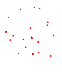
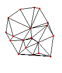
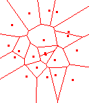
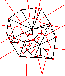
The SLIDE description above builds a terrain mesh over 20 randomly
generated points. The images below show the output of the Delaunay
and Voronoi algorithms in the XY-plane. The Delaunay triangulation
generates the triangular mesh. The Voronoi diagram is the planar dual
of the Delaunay triangulation. It divides the plane into zones each
associated with the input vertex which is the closest.
| Input |
Delaunay |
Voronoi |
Duality |
 |
 |
 |
 |
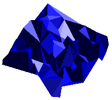
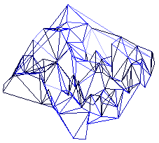
The images below show a second instantiation with 100 random
points. The Delaunay triangulation is formed in the XY-plane and then
the Z coordinates are restored creating a jagged terrain due to the
random input. This example shows how the terrain node might be
used to make simple models using laser range data.
| Solid |
Wire Frame |
 |
 |
generalface
The object and face primitives make it possible to
build arbitrary polyhedrons out of convex facets. Sometimes it is
much more natural to specify a shape using concave facets or facets
with holes in them. As these shapes are harder to operate on, it is
necessary to break them up into convex pieces, in most cases
triangles.
The generalface statement creates a triangular mesh given a
boundary set of non-intersecting oriented 2D contours. The triangular
mesh is created by computing the constrained Delaunay triangulation
(CDT) of the input contour edges. This construct is useful for
tesselating non-convex polygons. The algorithm which is used is the
2D y-monotoning algorithm. The generalface allows 3D input.
The 3D input must be transformed into the XY-plane where the
y-monotoning algorithm can be performed and then it is transformed
back to its position in 3D.
It is also possible to compute the
generalized Voronoi diagram of the input contours. Once the Voronoi
diagram is created, it is possible to create a set of offset
contours.
| SLIDE Definition |
tclinit Definition |
|
|
| SLIDE Defaults |
tclinit Defaults |
| generalface id
|
| |
type SLF_TERRAIN_DELAUNAY_
voronoi SLF_VORONOI_OFF
accuracy SLF_FLOAT
random SLF_OFF
offsets 0
offsetmin 0.0
offsetmax 0.0
drawcontours SLF_OFF
drawvertices SLF_OFF
drawCDT SLF_ON
drawoffset SLF_OFF
solid SLF_SOLID
surface SLF_INHERIT
shading SLF_INHERIT
lod SLF_FULL
ribbegin SLF_NULL
ribend SLF_NULL
|
| endgeneralface |
|
| slide create generalface id \
|
| |
-type SLF_TERRAIN_DELAUNAY_ \
-voronoi SLF_VORONOI_OFF \
-accuracy SLF_FLOAT \
-random SLF_OFF \
-offsets 0 \
-offsetmin 0.0 \
-offsetmax 0.0 \
-drawcontours SLF_OFF \
-drawvertices SLF_OFF \
-drawCDT SLF_ON \
-drawoffset SLF_OFF \
-solid $SLF_SOLID \
-surface $SLF_INHERIT \
-shading $SLF_INHERIT \
-lod $SLF_FULL \
-ribbegin $SLF_NULL \
-ribend $SLF_NULL
|
|
| Field |
Description |
| type |
The Delaunay triangulation algorithm which will be used to
create the mesh, see the
Delaunay type
for details.
|
| voronoi |
The algorithm which will be used to
create the Voronoi diagram, see the
Voronoi type
for details.
|
| accuracy |
The level of numeric accuracy which will be used to compute
the Delaunay triangulation and the Voronoi diagram, see the
accuray type
for details.
|
| random |
Whether or not to randomize the order of the input vertices.
This can have a great effect on the running time of some of the
algorithms.
|
| offsets |
Number of incremental offset contour sets to create.
0 <= offsets
|
| offsetmin |
Minimum offset distance value.
|
| offsetmax |
Maximum offset distance value.
|
| drawcontours |
Whether or not to draw the input contours.
|
| drawvertices |
Whether or not to draw the input vertex sites.
|
| drawCDT |
Whether or not to draw the CDT mesh.
|
| drawoffset |
Whether or not to draw the offset contours.
|
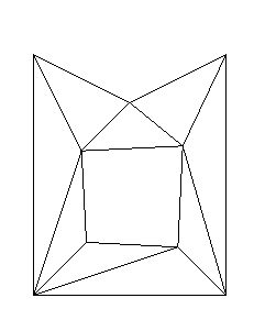
Example: Annulus
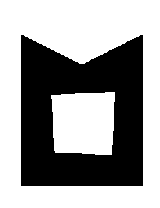
The annulus example shows a non-convex polygon which is bounded by
a concave outer contour with a single inner hole contour.
tclinit {
  package require slideui

  toplevel .slfWindow.ui

  CreateSLIDEGeneralFaceObject oGeneralFace
  set widget [CreateSLIDEGeneralFaceUI .slfWindow.ui oGeneralFace]
  pack $widget
}

point p0_0 ( 2 3 0 ) endpoint
point p0_1 ( 0 2 0 ) endpoint
point p0_2 ( -2 3 0 ) endpoint
point p0_3 ( -2 -2 0 ) endpoint
point p0_4 ( 2 -2 0 ) endpoint

point p1_0 ( 1 -1 0 ) endpoint
point p1_1 ( -0.9 -0.9 0 ) endpoint
point p1_2 ( -1 1 0 ) endpoint
point p1_3 ( 1.1 1.1 0 ) endpoint

generalface oGeneralFace ( p0_0 p0_1 p0_2 p0_3 p0_4 )
  contour ( p1_0 p1_1 p1_2 p1_3 )
  solid { expr $oGeneralFace(solid) }
  shading { expr $oGeneralFace(shading) }
  type { expr $oGeneralFace(type) }
  voronoi { expr $oGeneralFace(voronoi) }
  accuracy { expr $oGeneralFace(accuracy) }
  random { expr $oGeneralFace(random) }
endgeneralface
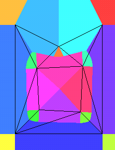
The table below shows the desired shape, a triangulation of this
shape, and a visualization of the Voronoi diagram of the input
contours where edges and vertices are Voronoi sites.
| Input |
Triangulation |
Voronoi |
 |
 |
 |
subdivision
A subdivision statement creates a closed triangular mesh
which can then be subdivided using one of a number of subdivision
techniques. The initial control mesh is defined by a set SLIDE nodes
which are instanced by the subdivision node. The control mesh
is created by hierarchically merging the facets defined by the
instanced geometry to form a fully closed mesh of facets. If this
merging process fails the unmatched boundary edges will be highlighted
by the renderer so that the can be repaired in the description file.
Once a closed mesh has been created a subdivision algorithm can be
applied to create an asymptotically smooth surface.
| SLIDE Definition |
tclinit Definition |
|
|
| SLIDE Defaults |
tclinit Defaults |
| subdivision id
|
| |
type SLF_CATMULL_CLARK
subdivisions 0
drawcontrols SLF_OFF
solid SLF_SOLID
surface SLF_INHERIT
shading SLF_INHERIT
lod SLF_FULL
ribbegin SLF_NULL
ribend SLF_NULL
|
| endsubdivision |
|
| slide create subdivision id \
|
| |
-type $SLF_CATMULL_CLARK \
-subdvisions 0 \
-drawcontrols $SLF_OFF \
-solid $SLF_SOLID \
-surface $SLF_INHERIT \
-shading $SLF_INHERIT \
-lod $SLF_FULL \
-ribbegin $SLF_NULL \
-ribend $SLF_NULL
|
|
| Field |
Description |
| type |
The subdivision algorithm which will be used to subdivide
the mesh, see the
subdivision type
for details.
|
| subdivisions |
The number of subdivision steps to apply to the control mesh.
|
| drawcontrols |
Whether or not to draw the control mesh in wire frame.
|
Example: Subdivided Octahedron
The SLIDE description below shows how to create and use a
subdivision node. The tclinit block creates a Tcl
associative array called oSubivision which has fields which are
manipulated by a Tk UI. The values in the oSubdivision associative
array will be used to control the subdivision node. The
include statement imports a SLIDE file which describes an octahedron.
The subdivision node links its parameters to fields in the Tcl
associative array. The subdivision node instances the
octahedron object which as its starting geometry. The
subdivision node can then apply one of the subdivision
algorithms to the geometry a specified number of times.
tclinit {
  package require slideui

  toplevel .slfWindow.ui

  CreateSLIDESubdivisionObject oSubdivision
  set widget [CreateSLIDESubdivisionUI .slfWindow.ui oSubdivision]
  pack $widget
}

include "octahedron.slf" # describes object oOctahedron

subdivision oSubdivision
  shading {expr $oSubdivision(shading)}

  type {expr $oSubdivision(type)}
  subdivisions {expr $oSubdivision(subdivisions)}
  drawcontrols {expr $oSubdivision(drawcontrols)}

  instance oOctahedron
  endinstance
endsubdivision
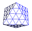
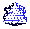
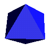
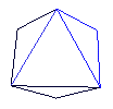
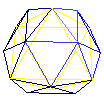
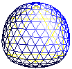
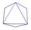
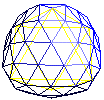
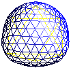
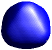
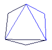
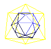
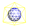
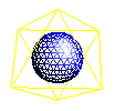
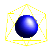
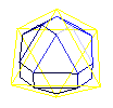
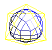
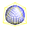
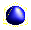
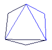
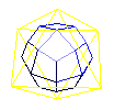
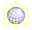
The table below shows the result of setting the parameters in the
Tk UI. The rows correspond to the different subdivision algorithms
which are supported. The columns correspond to the number of
subdivision steps which have been applied to the original octahedron.
Note that when zero subdivisions are applied the result is the
original geometry, so the result is the same for all the different
algorithms. The geometry is rendered in wire frame so that it is
easier to understand the basic recursion of the different algorithms.
Then a flat shaded image is included to show how smooth the result can
look. The original geometry or control mesh is rendered as a
reference in yellow wire frame over top of the subdivision surface
geometry.
| Subdivisions |
0 |
1 |
2 |
3 |
5 |
| Triangle |
 |
 |
 |
 |
 |
| Butterfly |
 |
 |
 |
 |
 |
| Zorin |
 |
 |
 |
 |
 |
| Loop |
 |
 |
 |
 |
 |
Doo
Sabin |
 |
 |
 |
 |
 |
Catmull
Clark |
 |
 |
 |
 |
 |
The first four subdivision types only work for input geometry
which has been tesselated into triangles only. The Triangle
subdivision type simply turns each triangle into four subtriangles.
This was mainly useful for developing the topological operations
necessary for performing the Butterfly, Zorin, and Loop subdivision
types. The Triangle subdivision is also useful for subsampling
triangulated geometry. One example of the utility of subsampling
triangles is creating highlights while shading.
The Butterfly and Zorin subdivision techniques are interpolating
schemes. They both use the same topologic subdivision step, but they
move the newly created points off of the original polygonal geometry
by a function based on neighboring vertices. Zorin's technique is an
extension to the simpler Butterfly technique. The interpolating
nature of these two techniques makes it difficult for them to create
smooth surfaces for arbitrary control meshes.
The Loop, Doo-Sabin, and Catmull-Clark subdivision types are all
approximating techniques. They move the newly created vertices as
well as the currently present vertices on each subdivision step. This
extra averaging allows these subdivision processes to create smoother
looking surfaces. Note that the approximating techniques yield
surfaces which are smaller than the control mesh where as the
interpolating techniques yield surfaces which are larger than the
control mesh. The approximating methods have the convex hull
property. The convex hull property guarantees that the final geometry
is completely contained within the convex hull of the control mesh.
Loop's algorithm uses the same basic triangle subdivision step.
Doo-Sabin subdivision is a generalization of quadratic B-spline
patches over irregular control meshes. Catmull-Clark subdivision is a
generalization of cubic B-spline patches over irregular control
meshes.
offset
An offset statement creates a mesh that can then be offset
using one of a number of offset techniques. The initial control mesh
is defined by a set of SLIDE nodes which are instanced by the
offset node. The control mesh is created by hierarchically
merging the facets defined by the instanced geometry to form a
connected mesh of facets. Once a mesh has been created an offsetting
algorithm can be applied to create a naive offset surface. The
current offsetting algorithms do not handle self intersections
properly.
| SLIDE Definition |
tclinit Definition |
|
|
| SLIDE Defaults |
tclinit Defaults |
| offset id
|
| |
type SLF_CATMULL_CLARK
height 0.0
width 0.0
drawcontrols SLF_OFF
solid SLF_SOLID
surface SLF_INHERIT
shading SLF_INHERIT
lod SLF_FULL
ribbegin SLF_NULL
ribend SLF_NULL
|
| endoffset |
|
| slide create offset id \
|
| |
-type $SLF_CATMULL_CLARK \
-height 0.0 \
-width 0.0 \
-drawcontrols $SLF_OFF \
-solid $SLF_SOLID \
-surface $SLF_INHERIT \
-shading $SLF_INHERIT \
-lod $SLF_FULL \
-ribbegin $SLF_NULL \
-ribend $SLF_NULL
|
|
| Field |
Description |
| type |
The offset algorithm which will be used to offset
the mesh, see the
offset type
for details.
|
| height |
The distance to offset the surface normal to the control mesh.
|
| width |
The distance to offset from the edges tangent to the control mesh. This applies for SLF_OFFSET_ANGULAR only.
|
| drawcontrols |
Whether or not to draw the control mesh in wire frame.
|
Example: Offset Octahedron
The SLIDE description below shows how to create and use a
offset node. The tclinit block creates a Tcl
associative array called oOffset which has fields which are
manipulated by a Tk UI. The values in the oOffset associative
array will be used to control the offset node. The
include statement imports a SLIDE file which describes an octahedron.
The offset node links its parameters to fields in the Tcl
associative array. The offset node instances the
octahedron object as its starting geometry. The
offset node can then apply one of the offset
algorithms to the geometry.
tclinit {
  package require slideui

  toplevel .slfWindow.ui

  CreateSLIDEOffsetObject oOffset
  set widget [CreateSLIDEOffsetUI .slfWindow.ui oOffset]
  pack $widget
}

include "octahedron.slf" # describes object oOctahedron

offset oOffset
  shading {expr $oOffset(shading)}

  type {expr $oOffset(type)}
  height {expr $oOffset(height)}
  width {expr $oOffset(width)}

  drawcontrols {expr $oOffset(drawcontrols)}

  instance oOctahedron
  endinstance
endoffset
dual
A dual statement creates a closed mesh and then creates the dual
mesh. The initial control mesh is defined by a set of SLIDE nodes
which are instanced by the dual node. The control mesh
is created by hierarchically merging the facets defined by the
instanced geometry to form a fully closed mesh of facets. If this
merging process fails the unmatched boundary edges will be highlighted
by the renderer so that the can be repaired in the description file.
Once a closed mesh has been created the dual mesh can then be created.
| SLIDE Definition |
tclinit Definition |
|
|
| SLIDE Defaults |
tclinit Defaults |
| dual id
|
| |
drawcontrols SLF_OFF
solid SLF_SOLID
surface SLF_INHERIT
shading SLF_INHERIT
lod SLF_FULL
ribbegin SLF_NULL
ribend SLF_NULL
|
| enddual |
|
| slide create dual id \
|
| |
-drawcontrols $SLF_OFF \
-solid $SLF_SOLID \
-surface $SLF_INHERIT \
-shading $SLF_INHERIT \
-lod $SLF_FULL \
-ribbegin $SLF_NULL \
-ribend $SLF_NULL
|
|
| Field |
Description |
| drawcontrols |
Whether or not to draw the control mesh in wire frame.
|
Example: Dual Octahedron
The SLIDE description below shows how to create and use a
dual node. The tclinit block creates a Tcl
associative array called oDual which has fields which are
manipulated by a Tk UI. The values in the oDual associative
array will be used to control the dual node. The
include statement imports a SLIDE file which describes an octahedron.
The dual node links its parameters to fields in the Tcl
associative array. The dual node instances the
octahedron object as its starting geometry. The
dual node then creates the dual mesh where facets become vertices and vertices become facets.
tclinit {
  package require slideui

  toplevel .slfWindow.ui

  CreateSLIDEDualObject oDual
  set widget [CreateSLIDEDualUI .slfWindow.ui oDual]
  pack $widget
}

include "octahedron.slf" # describes object oOctahedron

dual oDual
  shading {expr $oDual(shading)}

  drawcontrols {expr $oDual(drawcontrols)}

  instance oOctahedron
  endinstance
enddual
mirror
A mirror statement creates a closed mesh and then creates
the mirror mesh. The initial control mesh is defined by a set of
SLIDE nodes which are instanced by the mirror node. The
control mesh is created by hierarchically merging the facets defined
by the instanced geometry to form a mesh of facets. The mirror mesh is created by reversing the sense of all the facets.
| SLIDE Definition |
tclinit Definition |
|
|
| SLIDE Defaults |
tclinit Defaults |
| mirror id
|
| |
drawcontrols SLF_OFF
solid SLF_SOLID
surface SLF_INHERIT
shading SLF_INHERIT
lod SLF_FULL
ribbegin SLF_NULL
ribend SLF_NULL
|
| endmirror |
|
| slide create mirror id \
|
| |
-drawcontrols $SLF_OFF \
-solid $SLF_SOLID \
-surface $SLF_INHERIT \
-shading $SLF_INHERIT \
-lod $SLF_FULL \
-ribbegin $SLF_NULL \
-ribend $SLF_NULL
|
|
| Field |
Description |
| drawcontrols |
Whether or not to draw the control mesh in wire frame.
|
Example: Mirror Octahedron
The SLIDE description below shows how to create and use a
mirror node. The tclinit block creates a Tcl
associative array called oMirror which has fields which are
manipulated by a Tk UI. The values in the oMirror associative array
will be used to control the mirror node. The include statement
imports a SLIDE file which describes an octahedron. The mirror
node links its parameters to fields in the Tcl associative array. The
mirror node instances the octahedron object as its
starting geometry. The mirror node then creates the mirror
mesh where all the facets orientations are reversed.
tclinit {
  package require slideui

  toplevel .slfWindow.ui

  CreateSLIDEMirrorObject oMirror
  set widget [CreateSLIDEMirrorUI .slfWindow.ui oMirror]
  pack $widget
}

include "octahedron.slf" # describes object oOctahedron

mirror oMirror
  shading {expr $oMirror(shading)}

  drawcontrols {expr $oMirror(drawcontrols)}

  instance oOctahedron
  endinstance
endmirror


