The geometry of a gear tooth is described only once, but reused several times.
Solid Interchange Format, Networked CAD/CAM, Designer/Fabricator Interface, Rapid Prototyping
Under NSF sponsorship, we are developing a Solid Interchange Format (SIF) with which descriptions of desired parts can be transmitted efficiently and unambiguously from a designer to competing fabricators. SIF is a terse, human readable ASCII format providing a process- and resolution-independent description of the desired shape. It also explicitly captures some aspects of the part topology and of the original design intent, as well as information on precision and tolerancing. SIF is designed to carry enough information so that back and forth interactions between designers and fabricators can be reduced to a single one-way part submission after the designer runs standardized test programs to assure the consistency of the SIF representation and the manufacturability of the part with the selected fabrication process.
In the domain of digital VLSI (Very Large Scale Integrated) circuits, networked-based rapid prototyping has been practised for almost two decades. Starting on an experimental basis in the academic community in the early 1980's, "naive" designers unfamiliar with the details of integrated circuit processing were able to submit layout descriptions for digital MOS (Metal Oxide Semiconductor) circuit chips over the Arpanet to a few participating fabrication houses (Xerox PARC, Hewlett Packard, and others) and then receive completed and packaged chips a few weeks later. This was made possible by the fact that the MOS processes could be abstracted conceptually to the definition of a stack of geometrical layers that defined the structures on the completed chips. Simple rules defined the way in which combinations of geometrical features in these layers would form transistors, capacitors, interconnection lines, and vertical via holes. All that a designer had to do to create a chip with functional circuitry was to combine such geometrical elements according to a set of published layout rules. Beyond that, designers were shielded from tedious manufacturing details such as the use of primary and secondary fabrication masks, their polarities and exposure characteristics, the type of photo-resist used on the chips, as well as feature shrinking or over-etching during processing.
The geometries submitted by the designers express what they expect to see when looking at the finished chip. The patterns for each of the six to eight layers in some standard MOS process were originally described in CIF (Caltech Intermediate Form)[9], a simple and unambiguous interchange format that could easily be translated into the different geometrical primitives understood by the various mask making machines employed in those days. This medium-level geometry language describing the desired result of the fabrication process played a crucial role in streamlining the submission of designs. It contained all customer-specific information necessary to fabricate the designed chip, and there was no need for any "clarifying questions" from the fabricator. If the designers had done their homework properly, i.e., obeyed all the layout design rules, extracted the resulting circuitry from the specified geometry, and made a sufficient set of simulation runs with that circuit, then submission of the design for fabrication was a one-way communication, and the designer could expect to obtain a functional part.
This style of interaction between designers and fabricators has become commercially successful for digital circuits that do not push too close to the technological limits. With DARPA and NSF sponsorship, this approach to rapid prototyping of digital circuits was first institutionalized as "MOSIS" -- the MOS Implementation System at USC's Information Sciences Institute[2, 17]. Many commercial integrated circuit manufacturing companies later adopted it. This success story of networked manufacturing is the guiding light behind the current effort to provide a similar capability for certain types of mechanical parts.
As was made clear in the discussions at the NSF-sponsored workshops on "New Paradigms for Manufacturing" and "Design Methodologies for Solid Freeform Fabrication" in 1994/95[10, 11], the manufacturing of commercially viable mechanical parts offers fewer opportunities for the clean separation of concerns that has proven so beneficial in digital VLSI. The intensive coupling between concerns for functional form, mechanical strength, manufacturability, and aesthetics enforces a more holistic design of most mechanical parts or subsystems. Isolation from the details of fabrication are also more difficult to achieve, since the spectrum of available choices is so much richer, and the interaction between the different fabrication steps, fixturing, and tool selection can be very complicated.
There are some fabrication methods, however, that can offer a simple conceptual view to the designer. Foremost is the ever growing family of SFF (Solid Freeform Fabrication) processes, which includes Stereolithography (SLA)[8], Selective Laser Sintering (SLS)[3], Laminated Object Manufacturing (LOM)[6], Fused Deposition Modeling (FDM)[4], Shape Deposition Manufacturing (SDM)[7], 3D Printing[12], and several others. In all of these processes the object is built by depositing or solidifying material layer upon layer. Conceptually almost any shape can be constructed in this way, subject to the constraints imposed by the tolerances in coordinate addressing, the minimal thickness requirements for walls, and -- for some processes -- the addition of support structures needed for the construction of overhanging features. In many fabrication systems, the definition of such auxiliary structures has been automated, and the interface that the designer sees is simply a boundary representation of the desired shape.
A second class of fabrication methods that can be abstracted to mostly geometrical information is a purely subtractive approach, where regions of material are removed from an initial stock by cutting, drilling, and milling operations. In traditional manufacturing by machining, the fabricator also has to deal with the problem of fixturing, which demands considerable experience with judging the strength of the emerging part at any stage as well as knowledge of the exact tools that will be used. In CyberCut[18] the fixturing problem has been finessed to some degree by using Reference-Free Part Encapsulation (RFPE) [14] -- for instance in a bi-phase material such as Rigidax. This allows the machining of fragile parts with narrow cross sections and thin spars or membranes, and it avoids the complicated decisions of how to position, immobilize, and support the part for a particular operation. The conceptual user interface for this fabrication process consists of the specification of the stock geometry, and of the collections of holes and pockets to be removed while the part is accessed from a particular direction in its encapsulating block of Rigidax. During process planning -- typically done on the fabricator side -- machining operations are grouped by access direction and tool use, decomposed into subvolumes that can be removed with a single tool, and detailed tool-paths are calculated. The cavities produced by all the machining done from one direction are subsequently re-filled with Rigidax to restore an overall simple shape that can be accurately positioned and easily clamped for the next set of machining operations from a different direction. Again, a simple geometry language is sufficient to carry most of the part specification from the designer to the fabricator.
In all these cases, the dominant fabrication information is the final desired shape of the part, while its functional properties are implicitly defined by its geometry and by the material from which it is fabricated. Such a domain offers a streamlined one-way submission process from relatively "naive" designers who understand the fabrication process only at a conceptual level and who don't want to concern themselves with the details of individual tool selection for every machining operation, or with the calculation of the needed predistortion for a particular SFF process. A key component in such an environment is the language through which the designed geometry is communicated from the designer to the fabricator.
Under NSF sponsorship, we are developing a Solid Interchange Format (SIF) with which descriptions of desired parts can be transmitted efficiently and unambiguously from a designer to one or more different fabricators. SIF is primarily a medium-level geometry language that defines the desired final shape of a part. It lies at a higher level than the de facto standard, STL, used today to describe SFF parts, or the G&M codes that drive NC milling machines. On the other hand, it lies below the design-oriented specification languages that may describe a part by a set of parameterized features and by the mutual constraints between them. Designers may use a high-level CAD environment to create their shapes or generate them with a procedural program[16]. A particular instance of such a description, with all its parameters evaluated and constraints satisfied, may then be expressed unambiguously in SIF and transmitted to a fabrication house, where the SIF description, after some macro- and microplanning, gets converted into the low-level instructions that drive the actual fabrication machine.
The development of SIF was started in late 1996, and a first version has been used in research and in graduate courses at U. C. Berkeley. Here we report on those features of the language that we believe will survive future revisions. For up-to-date documentation of the current development state of the language, the reader should consult the web at URL http://www.cs.berkeley.edu/~ug/sif.
SIF is primarily a boundary representation. It specifies the position of all vertices in space, and then describes the planar faces supported by these vertices. Face connectivity can be derived simply and unambiguously from the shared vertices -- thus it is not stated explicitly in the interchange format. To facilitate the description of complex, tessellated surfaces, SIF also has constructs for multi-sided polygons, triangle-strips, and meshes. We are currently in the process of adding NURBS (Non-Uniform Rational B-Spline) constructs and an efficient representation for cylinders and spheres -- the most important curved surfaces. The language is easily extensible with the addition of new keywords. For a small example of the style of the language, see Figure 1, which describes a simple cube.
(* SIF Cube Description *)
(SIF_SFF 0 5
  (units (e 1 -2))
  (coord_precision (e 1 -5))
  (desired_accuracy (e 1 -3))
  (body 0
    (lump 1
      (shell 2
        (surface 3
          (v 10 1 1 1)
          (v 11 1 -1 1)
          (v 12 1 -1 -1)
          (v 13 1 1 -1)
          (v 14 -1 1 1)
          (v 15 -1 -1 1)
          (v 16 -1 -1 -1)
          (v 17 -1 1 -1)
          (f 10 11 12 13)
          (f 17 16 15 14)
          (f 10 13 17 14)
          (f 12 11 15 16)
          (f 11 10 14 15)
          (f 13 12 16 17)
        )
      )
    )
  )
)
|
| FIGURE 1. Sample SIF file defining a cube. The integers directly following the keywords body, lump, shell, surface, and v(ertex) are identifiers. |
SIF describes a desired part as a process- and resolution-independent ideal shape with some additional statements conveying acceptable deviations from this ideal, and other design intent information. The topological structure of the part is conveyed through its shared vertices and with explicitly stated nesting of its 3-D shells and 2-D contours. Nesting is expressed with suitable block structuring of the description, e.g., with a corresponding syntactic nesting of parentheses (see Figure 2). Surface and lump identifiers can be referenced for attaching surface and material properties to the geometry.
(* SIF Complex Face Description *)
(SIF_SFF 0 5
  (units (e 1 -2))
  (coord_precision (e 1 -5))
  (desired_accuracy (e 1 -3))
  (body 0
    (lump 1
      (shell 2
        (surface 3
          (v 10 4 2 0)
          (v 11 -4 2 0)
          (v 12 -4 -2 0)
          (v 13 4 -2 0)
          (v 14 3 1 0)
          (v 15 3 -1 0)
          (v 16 1 -1 0)
          (v 17 1 1 0)
          (v 18 -1 1 0)
          (v 19 -1 -1 0)
          (v 20 -3 -1 0)
          (v 21 -3 1 0)
          (face
            (loop
              (loop 14 15 16 17)
              (loop 18 19 20 21)
              10 11 12 13
            )
          )
	  (* Other faces would be defined here
           * to make the volume 2 manifold ...
           *)
        )
      )
    )
  )
)
|
|
FIGURE 2. The description of a complicated face in SIF with several holes;
the hole contours are syntactically nested inside the outer face contour. |
SIF uses a terse, human readable ASCII format. Compactness in representation is achieved by allowing hierarchical, iterative constructs, rather than only fully flattened descriptions. Instantiation is important for obtaining compact descriptions and convenient for expressing the intent of making several repeated surface areas exactly the same shape (see Figure 3), but it also causes some difficulties in the presence of numerical imprecision. In order to avoid problems with differing interpretations of floating point numbers by different machines, we have adopted the approach used by EDIF (Electronic Data Interchange Format)[5] to transmit only integer numbers (scalable with user-defined units). However, we still need to deal with the rounding errors that occur in precisely defined but imprecisely executed geometrical operations, such as a rotation of 45 degrees around the z-axis, which are inevitable when we allow the mechanism of instantiation. On the rims where different instantiated sub-portions of the surface come together, vertices may be instantiated via different algebraic expressions that produce different rounding errors. These non-manifold rim-vertices with slightly differing coordinates need to be merged to form a "water-tight" unambiguous boundary representation. SIF allows the designer to specify the expected maximum inaccuracy; this can be used to estimate the worst case range within which a program will have to look for other vertices that need to be merged.
|
|
|
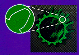
FIGURE 3. An example of instantiation in SIF.
The geometry of a gear tooth is described only once, but reused several times. |
The generic SIF language serves well to express the shapes that one might want to build with an SFF process. However, the language would be lacking to describe parts designed for fabrication by machining. A designer aiming at a CyberCut realization will typically have formed a mental plan for how the part can be fabricated from a piece of stock by removing pockets -- possibly from several different access directions. The part may even have been designed with our special web-based CAD tool that guides the designer through the conceptual process of subtracting pocket volumes from the original stock. It would be wasteful and counter-productive to withhold that information from the fabricator. Due to the limitations of the process considered, the representation of the high-level process plan can be naturally expressed in a limited form of a boolean CSG description called "Destructive Solid Geometry" (DSG) in which only difference operations are allowed, corresponding to the subsequent removal of individual holes and pockets[13]. If the part description were transmitted as a simple merged boundary representation, then the designer's plan would be lost, and all features would have to be rediscovered individually.
We have thus decided to create a separate dialect of SIF for such DSG-based fabrication methods. Paul Wright's group in the U. C. Berkeley mechanical engineering department has built an interactive on-line tool with which designers can develop a DSG description for a part to be built with CyberCut, while getting immediate feedback from this program about the validity of individual milling steps or the limited capabilities of a particular tool[15]. The final high-level processing plan is then captured in this SIF_DSG dialect and sent to other programs that will do the necessary macro-and microplanning before the part is machined on their 3-axis Haas milling machine.
A SIF_DSG file contains a description of the initial stock and a list of pockets with access directions. We currently support rectangular stock and machining access aligned with the major coordinate axes. A simple pocket with a flat bottom is specified as an extrusion of a closed 2D contour from the access face of the stock down to a fixed depth. Drill holes can be more concisely specified with a separate hole construct. Within their outer contours, pockets can have islands (bosses). Holes and pockets can be nested within other hole, pocket, or island descriptions (see Figure 4). By preserving the nesting hierarchy of features, it is possible for a designer to convey their process planning intent which should make the job of the manufacturer easier. Soon we will also support pockets with curved bottoms defined by one or more 3D tensor product NURBS patches. In this case, the pocket is the intersection of the NURBS surface, extruded upwards, and the pocket profile, extruded downwards from the stock face.
|
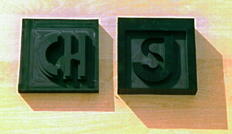
|
FIGURE 4. Two simple DSG parts that demonstrate the nesting of
pockets and islands within other features.
The "J" is an island within a rectangular pocket; the "S" is a pocket within the same rectangular pocket. |
Many individual decisions of what constructs will or will not appear in SIF have to be made. Our goal is for SIF or its dialects to be capable of efficiently and unambiguously describing a large domain of parts that can be fabricated with SFF and CyberCut without approximation. Moreover, information that may be useful for the actual fabrication and that was worked out laboriously by the designer should not get lost when the design is captured in the interchange format.
Consider the situation where a cylindrical hole needs to be cut through a complicated fractal shape that is to be manufactured with SFF. It would be computationally expensive to calculate all the trimmed NURBS patches that form the intersection of the cylinder wall with the fractal solid, and it would unduly increase the size of the description. Therefore we are in the process of adding some boolean CSG constructs to the SIF language. It is clearly beneficial to keep the cylinder as a separate CSG sub-tree when we plan to create the hole with an actual drilling operation after the fractal part has been built with SFF. But even if we plan to build the CSG combination directly with SFF, it may be more convenient to keep the cylinder primitive separate and to do the necessary boolean subtractions in 2D as each layer is formed in the SFF process.
Another future extension of SIF may include a volumetric representations using voxels -- just like PostScript[1] has the capabilities of including bit maps in addition to its line and curve drawing features. This feature would be useful for making SFF models of data gathered from a 3D scanning source such as MRI, or for specifying the microstructure of a non-homogeneous part.
A new interchange language on its own provides little incentive for adoption by the designer/fabricator community, unless it provides important new capabilities that were not previously available, or if it offers a marked increase in convenience. The SFF community has learned to live with STL in spite of all its serious shortcomings; for example, to describe a smooth sphere, hundreds of thousands of individual triangles have to be transmitted, each one with all its vertex coordinates explicitly defined -- so each vertex coordinate gets transmitted an average of six times. In addition, every triangle has to have a face normal, even though this information gets ignored by almost all tools. The inclusion of an efficient triangle mesh construct, or better yet, of exact NURBS patches or a compact one-line "sphere" construct, offers a strong advantage in this case. For simple faceted parts, the advantages may not be so dramatic.
To increase the usefulness of SIF, we are also working on an infrastructure and on tools to support SIF. We are building prototype converters between SIF and a small number of existing interchange formats, such as ACIS.sat and STL. We are also developing some key software modules that can become the kernels of many SIF-based tools needed at this design/manufacturing interface. For checking correctness and consistency, and for some limited optional cleanup of boundary representation descriptions coming from less structured design tools, we are developing programs that check whether the shape specified in the SIF file is indeed a closed solid, identify all non-manifold edges, and attempt to close cracks by merging non-manifold vertices that lie within some small distance epsilon of each other. To handle large designs with millions of polygons, we are investigating approaches to building an efficient, non-memory resident radial edge data structure, which will be used to support a robust slicer to produce the parallel slices needed by SFF machine controllers. Specifically for SFF processes, we will develop a minimum dimension checker that a designer can run on a SIF file to assure that all features are within the tolerances of the process chosen.
We believe that SIF will help to streamline the transfer of part descriptions from designers to fabricators. In many cases this should be a simple one-way transfer. Designers should run the verification software to check their files for cleanness and consistency before transmission. They should inform themselves about the capabilities of a particular process and the tolerances within which they can expect to get their parts realized, and run the minimum dimension checker on their part descriptions to confirm that those tolerances are suitable. They can then set a statement in the SIF file that expresses acceptable deviations from the ideal shape transmitted. With such a protocol to ensure consistency manufacturability, a design submission to a fabricator can indeed become a one-time, one-way operation.
This work was supported in part by NSF grants MIP-96-17995, MIP-96-32345, and CDA-94-01156.