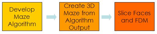
Figure 2.1: Procedural Design Path
Procedural Design
and Prototyping of a Rolling Ball Maze
Athulan Vijayaraghavan
and Adarsh Krishnamurthy
Project Summary
We procedurally design and prototype a three-dimensional rolling
ball maze. This is a variant of a conventional 2D rolling ball maze by
mapping the maze onto the faces of a cube. An algorithm was implemented
in MATLAB to create the three-dimensional maze, and was based on the
recursive backtracker algorithm. The maze data was exported to the ACIS
kernel where a solid model was created using the maze paths from the
algorithm. Finally, the faces of the model were independently
prototyped on a STRATASYS 1650 Fused Deposition Machine and assembled
to create the functional rolling ball maze.
Introduction and Motivation
Procedural Design
Generating the Maze
Solid Model Creation
Prototyping using Fused
Deposition Modeling
Results
Design for Manufacturing
Insights
Related Work and Bibliography
1 Introduction and
Motivation
Procedural methods are very useful in the design and manufacture of parts with a high degree of complexity. Procedural design involves applying a sequence of parameterized steps to realize the fully designed part. These methods are especially useful if the part design is cumbersome and labor intensive. In this project, we procedurally design a 3D rolling ball maze. A rolling ball maze is a puzzle-based game, where the objective is to move a spherical ball through a 2D maze. The maze is adequately complex so that the game engages the player. In our 3D rolling ball maze, a continuous, integrated maze is mapped on to the faces of a cube. The objective remains the same, the player moves (or rolls) a spherical metal ball from a designated "start" position in the maze to an "end" position. The 3D maze is more challenging as the maze wraps around the faces multiple times. In addition, the player cannot see the entire maze at any point of time further increasing the complexity of the maze. The motivation of this work was to apply procedural methods to design an engaging (and entertaining) device. The final output of this work was a fully functional, three-dimensional rolling ball maze. The next section describes the actual steps in the design and prototyping process.
The maze is designed and prototyped in a sequence of three steps (Figure 2.1). In the first step, the maze is logically generated and stored in an appropriate data structure. This data is then read and converted to a solid model in a CAD environment. Finally, the CAD model is prototyped in a rapid-prototyping machine. The requirements for each of the procedural steps are as follows:
Several algorithms to create 2D mazes have been described in the
literature [Pullen, 2006]. These algorithms create mazes either by
drawing walls or by breaking walls. In the former case, a "blank" maze
is taken and walls are selectively placed to create paths. In the
latter case, a "full" maze with all cells enclosed by walls is taken
and the walls are selectively removed to create paths. The generated
mazes are usually rectangular, and their edges do not wrap. However, to
create a 3D maze, we need a non-rectangular maze with connected edges.
We have modified a standard 2D maze algorithm - called the Recursive
Backtracker - to create a 3D "wrapped" maze.
Choosing the
Maze Algorithm
We first tried implementing the Kruskal Algorithm to create the 2D
maze. This algorithm - while creating a complex maze - did not create a
sufficiently non-trivial maze. The maze was very "stubby" and it was
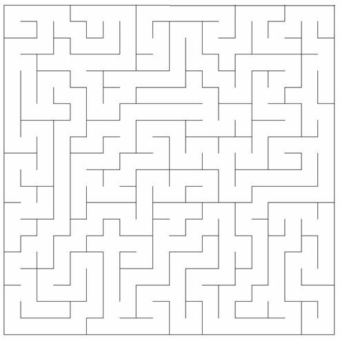
easy to find a solution for a path through the maze. Figure 3.1 shows
the output from Kruskal's algorithm for a 10x10 maze. Notice the large number
of short, stubby maze segments.

Figure 3.1: Maze output from
Kruskal's Algorithm
The Recursive Backtracker (RB) algorithm was selected due its
superiority in generating long "rivers." Rivers - in mazes - denote the
continuous paths that can be traced in a maze. The RB algorithm
generates mazes with the longest rivers [Pullen, 2006]. Moreover, we
are trying to generate only "perfect mazes." In a perfect maze, there
exists a path from any one cell to any other. This also implies that
there are no ``islands'' in the maze, which isolate a region. Since the
RB generates only "perfect" mazes, it satisfies this requirement as
well.
The algorithm for the RB algorithm, which will generate a 2D
non-wrapping maze, is as follows:
Adaptation to 3D
Adapting this algorithm to 3D involves generating a list of
neighbors for any arbitrary cell on the face of the maze, as well as
finding the common edge between these two faces. This is easy in 2D as
finding the neighbor and the common wall can be done using numerical
manipulation of the wall and cell indices. This is not possible in 3D
as there is no standard method for generating indices for the cells or
the walls. Instead, a brute force technique is used to perform these
two operations. A master list of all the cells in the maze is first
generated, which also identifies the corner vertices of the cell in
Cartesian coordinates. As we also need a way of tracking the walls that
break to generate the maze, a second list of all the edges in the maze
is generated. This edge information is stored by listing the vertices
of the edges. To look for the neighbor and the common wall of the
current cell, the edges of the current cell are searched against the
edges of all the cells in the maze. The maze with the common edge is
then identified as the neighbor. To "break" the common wall, the common
edge is removed from the edge-list of the maze. Thus, the edge-list of
the maze begins with a list of all the edges, but after the algorithm
is complete, contains the list of active walls in the maze.
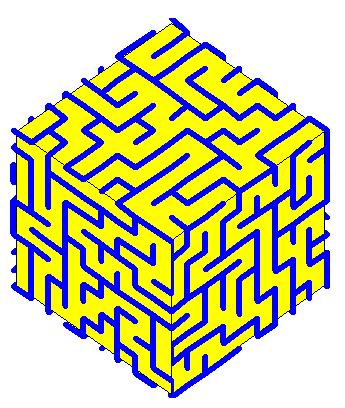
This modified algorithm was also implemented in MATLAB, and the
script can be found here. Figure 3.3 shows the
output of this algorithm for a 9x9x9 maze.
The next step in the procedural modeling of the maze cube was to generate the solid model of the cube from the output edge-list generated in MATLAB. We require the solid model to be watertight for ease of manufacturing.. Hence, the major requirement for choosing a solid modeling package is that it should handle Booleans effectively. ACIS, a solid modeling kernel is one such package. It has very good Boolean algorithms and it has the option to perform regularized Boolean operations as well. ACIS is a kernel, and its functions are accessed through C++ API function calls.
A program was written in C++ that takes in the input edges from the
MATLAB output file and converts it into a solid model. Since all the
edges are axis aligned, we move the two endpoints by half the final
solid edge width in the respective directions. Thus, each edge is
converted to a solid parallelepiped. Finally, a union of all these
parallelepipeds is created to form the solid maze. This is shown in
Figure 4.1. We also then add the six plates to form the base of each
face of the maze. The C++ program for this is available here.
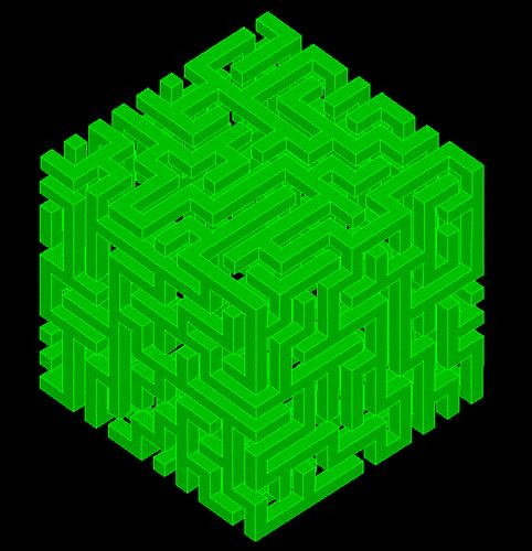
Figure 4.1: Solid Maze from ACIS
Once the maze is created, it is then saved as an ACIS SAT file,
which is one a standard CAD file format. This SAT file is then read
into SolidWorks for further procession which will be discussed in the
next section.
5
Prototyping with Fused Deposition Modeling
Fused Deposition Modeling (FDM) is a rapid prototyping technology that can be used to create thermoplastic parts from STL descriptions of solid models. We used a STRATASYS 1650 FDM machine for prototyping the rolling ball maze. The ACIS implementation discussed in the previous section produces a SAT file as output. Instead of directly converting this to the STL format for prototyping, we chose to post-process the solid model in SolidWorks. We did this because creating one full maze-cube will result in a waste of material as the interior; the interior of the maze is hollow and prototyping this will use up a lot of support.
Instead, we chose to slice the maze into the six faces in SolidWorks and then prototyped them individually. Following this, the maze was assembled by simply gluing the faces together. In the first implementation, we sliced the maze cube at 45-degree chamfers from the edges so that the joints of the assembly will coincide with the edges in the cube, making them appear seamless. Figure 5.1 shows the assembly of such faces. This method was not entirely successful as there were some small wall features at the edges of the individual faces that were being supported with very little base material. These wall features broke off during assembly resulting in an incomplete maze. Some of these features are shown in Figure 5.2.
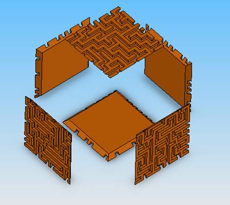
Figure 5.1: Assemble of Diagonally
Cut Faces
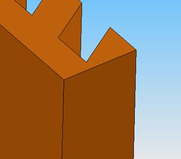
Figure 5.2: Small Wall Features in
Edges
In the next implementation, we choose to slice the faces into two large squares, two small squares and two rectangles. This method does expose a seam, but all the generated features are very stable during assembly. Figure 5.3 shows the exploded view of such an assembly.
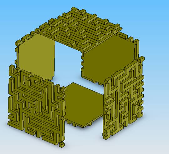
Figure 5.4: Assembly of Cut Faces
To prototype these faces, they were laid flat in an assembly and the STL file of the entire assembly was created. It was then exported into QuickSlice and prototyped in the FDM machine. The unassembled faces from the FDM machine are shown in Figure 5.4.
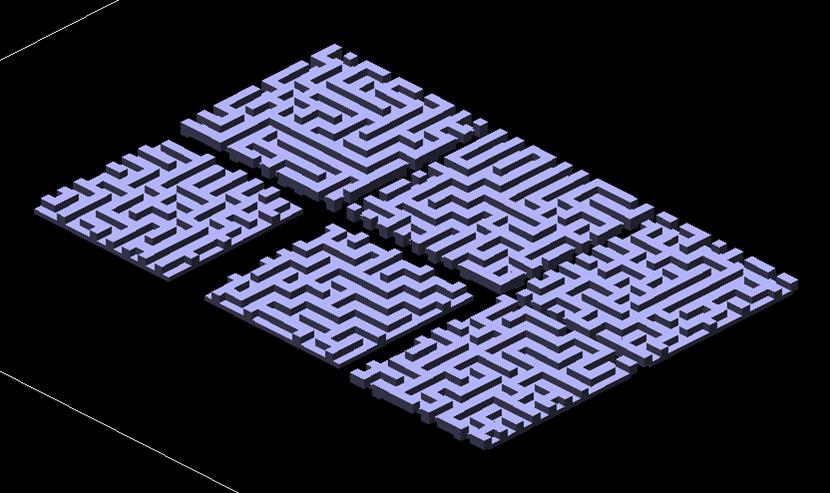
Figure 5.4: Faces Laid in-plane in
QuickSlice
Finally, using ABS glue the faces were assembled making sure that the maze lined up correctly. The fully assembled maze was placed into a specially chosen plastic shell that can easily be opened up. A hole was drilled into the plastic shell to denote the "end" of the maze puzzle.
We chose the dimensions of the maze based on complexity, and
availability of a plastic shell. We wanted enough cells to make the
maze very complex, but it had to fit into a plastic shell so that it
can actually be played without the ball falling out. We identified two
plastic shells which were appropriate, one with a side-length of 2.88"
and the other with a side-length of 3.88". We chose the 2.88" cube as
it would take lesser time to prototype. The thickness of the walls was
set equal to the width of the paths. Using a wall thickness (and path
width) of 0.15", a 9x9x9 maze could be prototyped to fit into the 2.88"
cube. The maze faces were placed into the plastic shell and a hole was
drilled in one point in the shell to serve as an "end" to the puzzle.
A 1/16" steel ball was introduced at a random location before the
plastic shell was placed and the objective is to get the ball out of
the maze. Having only an "end" position allows more flexibility in
playability as new scenarios can be created simply by putting the cube
in a different orientation in the shell.
The final, fully completed prototyped to these specifications can be seen in Figure 6.1.
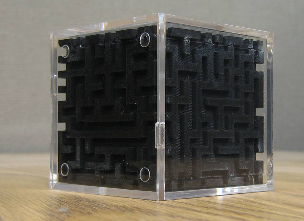
Figure 6.1: Assembled Maze
The solid model that was developed in section 5 is valid only if the part is to be prototyped using rapid prototyping methods. However, if the maze cube has to mass manufactured using processes like injection molding, certain additional steps have to be performed to make the model suitable for these operations. One of the basic changes that has to be included in solid modeling is the inclusion of draft angles to the model. Draft angles are essential to remove the part from the mold after the part cools down. Figure 7.1 shows a part of the maze with draft angles. However the figure shows an exaggerated draft angle for the purpose of visualization. In actual practice a draft angle of 1-2 degrees is enough.
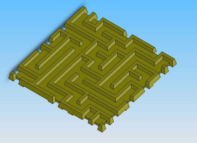
Figure 7.1: Model with Draft Angles
Another issue that has to be taken care is the one with respect to the assembly of the maze. Since the maze can be assembled only in one way for proper integration of the faces, there should be some method for ensuring this particular configuration during assembly. To aid in the assembly process asymmetric pegs can be added in the maze parts so that they fit together in only one configuration. Figure 7.2 shows a possible design with these pegs.
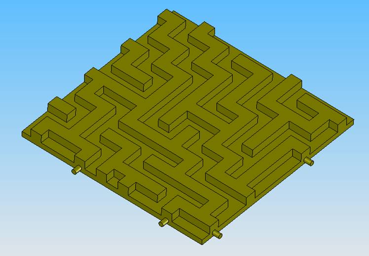
Figure 7.2 Model with asymmetric pegs
This project employed several different programming and modeling
packages to create the physical maze prototype. We created the logical
maze in MATLAB, made it into a solid model with a C++ program using the
ACIS kernel, created an assembly of faces from the solid model in
SolidWorks and finally prototyped using QuickSlice. The quirks of all
these packages had to be addressed, especially when the data generated
from one package was being read in another. It would have been much
quicker - especially for a full procedural algorithm - to have done
this all in one package such as C++. The procedural pipeline was quite
slow and there was plenty of room for error, especially in the physical
dimensions. Although this was fine for a prototype, it would be
beneficial to move to a single package such as C++ (with ACIS
support) for large-scale implementations.
[Pullen, 2006] Walter D. Pullen, "Think Labyrinth: Maze
Algorithms",
http://www.astrolog.org/labyrnth/algrithm.htm, Accessed Feb -
May 2006.
This website had excellent resources
on different types of maze algorithms including the Recusrive
Backtracker algorithms.