CS 285: SOLID MODELING
Lecture #4 -- Mo, Feb. 4, 2002.
PREVIOUS < - -
- - > CS 285 HOME < - -
- - > CURRENT < - -
- - > NEXT
Preparation
Think about the strength and weaknesses of various geometry representations that you know
for the following task domains:
- A) Design front ends and design languages
-- Key constructs that are easy to use by the designers.
- B) Datastructures for manipulation, modification, analysis
-- Full connectivity to nearest neighbors for efficient modification.
- C) Shape capture for fabrication, interchange formats
-- Primitives that can readily be interpreted by the fabrication machines.
Demonstration of Various Sample SLIDE Programs
A) Design-Level Representations
- (Parameterized) Primitives
Cubes, spheres, cylinders, cones, ...
Look at the
SLIDE Language.
-
CSG -- Constructive Solid Geometry
Combine solids with regularized boolean operations
-
B-rep, Boundary Representation
The surface of the solid described as a collection of planar polygons
and/or curved (spline) patches.
Subdivision surfaces !
-
Voxels
Partially occupied array of solid volume elements.
- Instancing
--> This is the primary way to enforce symmetry in a design.
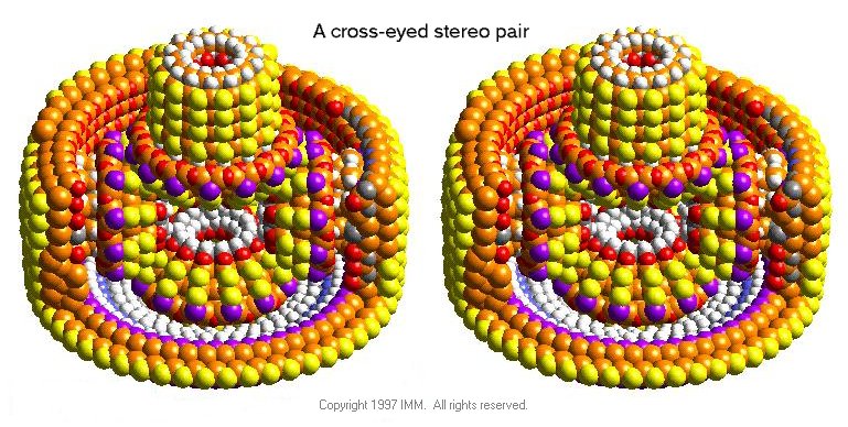
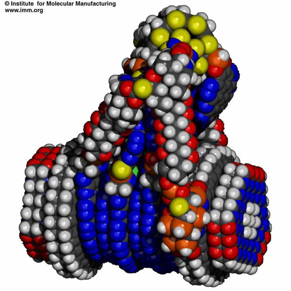
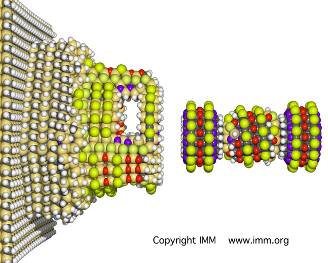
Atoms for
Nanotech Machines (
Differential Gear,
Motion Controller,
Atom Pump )
Parametrized primitives, previously defined objects, ...
- Parameterized objects, "auto-shapes"
2D: drafting symbols: n-gons, stars, "banners", ...
(available in most drawing programs).
3D: gear wheels, ...
(often custom-built, not yet readily available).
- Features for manufacturing
Through-holes, sink-holes, pockets, slots, shoulder pockets, ...
(No consistent nomenclature or definitions; should also be parameterized).
- Procedural generation
Spline patches -- defined by their type, control points, ...
Sweeps -- defined by cross section and sweep path.
L-systems -- parameterized instantiation based on expression trees.
Wavy surface of the sea, fractal mountains, ...
- Procedural shape modification
Edge bevelling or rounding.
Subdivision -- procedural smoothing, related to splines.
-
Structure of a design
Scene hierarchy (logical/functional).
Dynamic grouping during editing.
Constraints -- (e.g., Pro-E.)
-
The SLIDE Language
combines many of the above representations.
Many of the statements that have to do with rendering
can be ignored for CS285.
How to convert between these different representations ?
If you could have only ONE of the above paradigms -- which one would you choose ?
B) Data Structures for Solid Modeling
-
Non-hierarchical Boundary Representations
- Winged-edge data structure for orientable 2-manifolds (Baumgart)
- -- every edge connects to exactly two polygons, one on each side.
- Radial-edge data structure for non-manifolds (Weiler, UniGrafix)
- -- edges can connect to arbitrarily many polygons.
- Quad-edge data structure (Guibas and Stolfi)
- -- a dual/symmetric treatment of vertices and faces.
- Polygon soup ( .STL)
- -- not really a "data structure" -- but useful for "display lists."
- Cellular/Simplex Decompositions
-- the 3D equivalent of a triangulated 2D polygon.
-- finite-element meshes for structural analysis.
-- (possible project: generate these directly in SLIDE for sound analysis, e.g., bells).
-
Voxel-based Representations
-- for 3D raster data from ultra-sound or Magnetic Resonance Imaging (MRI).
-- also important as a general spatial reference frame when data is unevenly distributed.
"Tabulates" spatial occupancy. For efficient encoding use:
- Run-length encoding
- Octrees
- Wavelet-based (kD-tree-based) generalizations
Which is the right one for what purpose ?
C) Interchange Formats for Fabrication
=== We will do this at a later time, after I have told you something about fabrication ===
-
IGES -- Graphic Exchange Standard
originally for technical drawings;
true 3D added later.
-
.STL
low-level driver for SLA (Stereolithography) machines;
--> defacto standard for SFF (Solid Free-form Fabrication);
- -- wordy, redundant, potentially inconsistent, unclear semantics of polygon orientations.
Example: a cube in .STL
-
ACIS (Spatial Technologies)
a general solid modeling kernel,
allows dump of the complete data structure;
- -- this is not really an interchange format.
-
SIF -- Solid Interchange Format
primarily for SFF (Solid Free-form Fabrication).
Example: A cube in SIF (strawman) version 0.5, when complex faces were still OK.
Example: A cube in SIF 2.0, the simplified clean replacement for .STL.
-- Will SIF make it in the real world ?
-
Other SIF Dialects
- For machining: SIF_DSG (Destructive Solid Geometry)
- For layered manufacturing (SLA, SLS, FDM, 3D-Printing, ...): L_SIF
Comparison of various formats
Current Homework Assignments:
Next Homework Assignments:
PREVIOUS < - -
- - > CS 285 HOME < - -
- - > CURRENT < - -
- - > NEXT
Page Editor:
Carlo H. Séquin