CS 184: COMPUTER GRAPHICS
PREVIOUS
< - - - - > CS
184 HOME < - - - - > CURRENT
< - - - - > NEXT
Lecture #21 -- Mon 4/13/2009.
Questions that I did NOT ask on the Midterm-Exam:
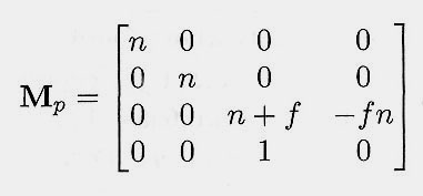
What happens to the mid-plane between "n" & "f"
in the transformation performed by
Shirley's perspective matrix Mp ?
I.e., give the equation for the plane z = (n + f)/2
after transformation with the matrix Mp
and subsequent homogenization to 3D.
Where does the same plane end up
after the complete perspective transform
into the full (+/-1) canonical view cube ?
|
|
How to find the solutions: Transform some key sample points by the above matrices and see what happens ...
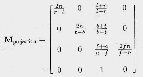
Wrap-up of Perspective Projection: from this to this !
Shirley breaks the whole perspective transformation into three easy to understand steps:
1.) The view transformation that standardizes arbitrary camera positions and gaze directions into the origin and down the z-axis;
2.) The perspective matrix that un-warps the view frustum into a rectilinear brick (as one would get in a parallel projection);
3.) The mapping to the canonical view volume (a full cube with planes at +/-1) for easy clipping and depth comparisons ...
Together they formt he perspective projection matrix.
Review Chapter 7 again and learn how to use these matrices !
SOME CLARIFYING QUESTIONS:
Is the perspective image of a straight line is also a straight line ?
Use parameterized representation;
apply distributive law to transformation (linearized by the use of homogeneous
coordinates!).
P(t) = (1-t)*A + (t)*B
P'(t) = T*P(t) {for every point} = T*[ (1-t)*A + (t)*B ]
Because T is described with a linear matrix: P'(t) = (1-t)*T*A + (t)*T*B
P'(t) = (1-t)*A' + (t)*B' { with A' = T*A, and B' = T*B }.
So, if all this is so nice and linear ...
Why can the perspective images of line segments
go through infinity (if we don't clip) ?
Is the image of the mid-point of a line segment, in the middle of the imaged line segment ?
Is the perspective transformation really a linear operation ??
( -- Only in 4D; not in 3D after division!)
Vanishing Points and Vanishing Lines
The vanishing point is the perspective image of the point where a bundle
of parallel lines seem to converge. (Example:
Road)
We can find
this point by shooting a ray in the direction of the parallel bundle
and finding its intercept with the imaging plane.
Ray bundles parallel to the imaging plane do not have vanishing
points!
If you have multiple bundles of parallel lines in the same plane,
then all their vanishing points form a vanishing line (or a "horizon")
-- example:
"2-runway airfield".
Vanishing line = "horizon" of a plane = collection of the vanishing
points of all the lines in the plane.
Parallel planes have the same vanishing line.
To find
their vanishing line, pick the one through eye point and find intersection
with imaging plane.
N-Point Perspectives
Art schools make a big fuss about drawing worlds with 1-,
2-, or 3-point perspectives,
showing the corresponding number of vanishing points for bundles of
parallel lines.
However, this really only makes sense for "brick worlds" with three
sets of dominant directions.
In worlds with more than 3 major directions in which we find many edges,
each such bundle of parallel lines can produce
its own vanishing point.
The only situation when such a bundle does not produce a vanishing
point is when it lies parallel to the imaging plane.
Thus an octahedron
with 6 pairs of parallel edges can have 6 vanishing points,
and can thus be rendered in "6-point perspective" !
What is the minimum number of vanishing points that it can produce
?
-- Well, it can be oriented in such a way that one of its triangular
faces lies parallel
to the imaging screen;
then 3 parallel bundles do not have a vanishing
point, and there remain only three.
Similarly, an icosahedron
(20 triangles) with 15 pairs of parallel edges can have
a maximum number of 15 vanishing points and a minimum number of 10.
(5 edges lie in the same plane at the base of a five-sided pyramid and
they can thus all be simultaneously parallel to the image plane and
loose their vanishing points.)
What are the maximum and minimum number for a n-sided regular prism
? -- or for a dodecahedron
(12 pentagons, 15 edge pairs)... ?
Parallel Projections
Orthographic (plan-view, elevation, isometric): The
direction of projection (dop) is parallel to the n-axis of the VRCS.
Oblique (cabinet, cavalier): The direction of projection
(dop) is skewed with respect to the n-axis of the VRCS; different
amounts of foreshortening of the 3rd dimension.
Perspective Projections
"N-point perspectives"
(N=1, 2, 3 ...)
Clipping and Perspective
Review:
The need for near-plane clipping
1.) Do it in z first, to avoid above wrap-around problem, and then do more
clipping later in 2D;
This is conceptually plausible, but inelegant, since
it involves two different clipping steps.
2.) Do it in 3D on the canonical view frustum;
This is doable, but it involves more complex expressions for the sides of the frustum.
3.) Do
it in 4D in the normalized frustum in the space of the homogeneous coordinates;
This is the most elegant solution, it avoids
unnecessary expensive coordinate divisions by w, and the clipping
process has very simple numerical values.
(You don't need to know the detailed math, just the costs and benefits of doing it in 4D)
Comparing Two Different Rendering Paradigms:
The Classical Rendering Pipeline (object space):
Geometric Model
Camera Placement
Perspective Projection
Visibility Calculation
Illumination
Rasterization
Display
Ray-Tracing Pipeline (image space):
Geometric Model
Camera Placement
Decide on Image Resolution (# of pixels)
Ray Casting / Visibility Calculation / Rasterization ==> all in
one !
Light-source Probing
Visibility Determination, Hidden Feature Elimination
The Problem:
Some front faces can hide other front faces; we need to determine what should be drawn on the display.
Concept of "Depth Complexity": How many things are stacked behind
each other on average ?
Solution #1: Ray Casting:
-- Cast a ray from the eye through each pixel into
the scene,
then determine what surface gets hit first (display
that color).
Solution #2: Painter's Algorithm:
This is one of several "List-priority Algorithms"
-- Depth-sort all front-facing polygons (e.g.,
by their closest point, or by their centroid); then (over-) paint them back-to-front.
-- BUT: Complete depth sorting is not be possible when
there are cyclic overlaps; then we need to break polygons into smaller parts.
See also: Binary Space Partition Tree (Shirley Ch. 8.1).
Solution #3: Horizon-Line Algorithm:
Suited primarily for height functions and for terrains.
-- Paint slices through the terrain function from front-to-back.
-- Keep an up-to-date upper horizon
= silhoutette edge Max-y(x); the area below this horizon is shadowed
out;
-- Only draw new elements above the current horizon.
Solution #4: Z-Buffer
The z-buffer is a 2D array of storage elements that stores for each
pixel (R,G,B)color and a z-depth.
-- Paint all triangles (one at a time) into the
z-buffer (using scan-line-based raster filling; the front-most pixel and its depth and color
will be retained -- and finally displayed.
-- The z-depth of each pixel can be efficiently
calculated by linear interpolation, i.e., by fixed incrementation
in y and in x (since we assume all polyhedron faces to be planar).
Results of Mid-Term Exam
Max=144,
Min=53, Mean=99.3, Stdev=22.7; Approximate evaluation: A=120-130; B= 90-100; C=60-70.
Comments on last question. Review of reflection, refraction, raytracing. Nice demo of Snell's law.
More discussion next time ...
Reading Assignments:
Review: All exam questions -- in particular those that you did not get perfectly right.
Review: Shirley Ch. 8.
Programming Assignment 8: due (electronically submitted) before Wednesday 4/15, 11pm.
PREVIOUS
< - - - - > CS
184 HOME < - - - - > CURRENT
< - - - - > NEXT
Page Editor: Carlo
H. Séquin