How to Make a Flexible Curved Tactile Display
Disclaimer: The process and files are provided AS IS and
unsupported. There is no guarantee that this process will work for you.
Many hours have been devoted to developing this process and design, so
there is a lot of experience involved in making these tactile displays.
Notes
This webpage is basically a reproduction of Appendix B of my
dissertation, available for download on the sidebar. The dissertation
has descriptions of the following:
Electronics and pneumatics used to drive the tactile displays
The tactile sensors used to provide data to the tactile displays
The psychophysics testing and results
We started developing and refining this process no later than February 2000.
Previously, we made a flat tactile display that is discussed in an
ICRA
2000 paper.
Full resolution pictures can be seen by clicking on any picture.
Use of pictures for anything other than personal use by permission only.
Materials and Equipment
- Computer with SolidWorks
- Dow Corning HS II Silicone Rubber Base
- Dow Corning HS II Colored (pink) Catalyst, 10:1
- 3D Systems
ThermoJet
- 2mm Outer Diameter Silicone Tubing (See
New Age Industries
part number 2810458)
- Plastic cup, Scale, and Vacuum Chamber
- Miscellaneous clamps, weights, flat plexiglass pieces, and X-Acto knife
The whole fabrication process takes approximately 2 days, as it takes 24
hours for the HS II to cure.
Mold Preparation
Using the Solidworks files available for download on the sidebar, we use the
ThermoJet to create the sacrificial mold. Have Solidworks save the designs
as STL files that the ThermoJet can take as input.
Carefully slide the pin pieces into the base. It will be a really
snug fit. The mold is shown below:
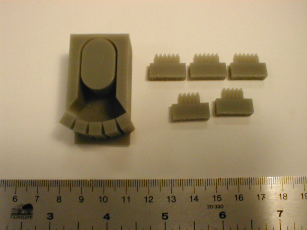
This mold makes a tactile display with 28 elements spaced 2mm apart and
hexagonally packed (6-5-6-5-6).
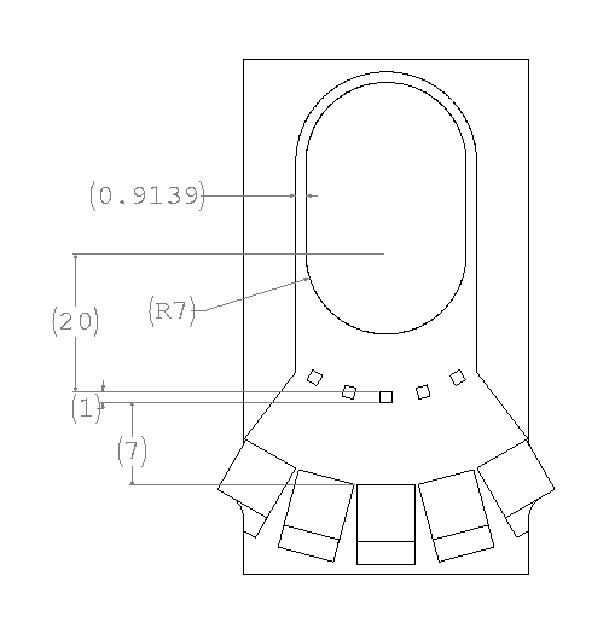
The finger interface has a 14 mm diameter. The pin height
determines the thickness of the rubber layer between the air chambers
and finger. In our case, we use a 5.5 mm pin height to achieve a 0.5 mm
membrane thickness.
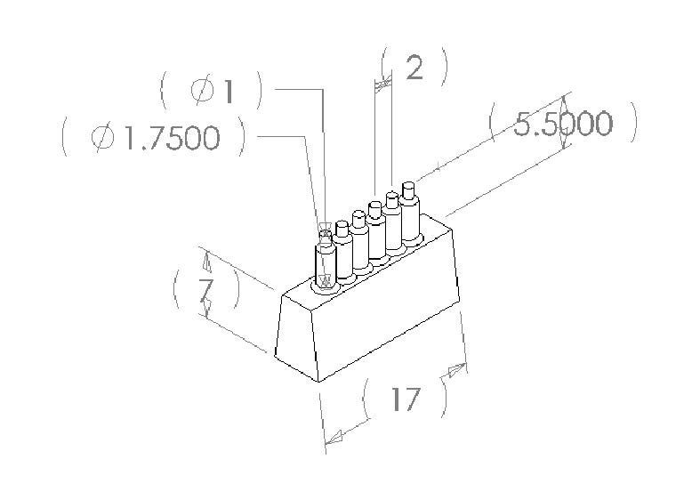
The pins have a 1 mm diameter top section and a 1.75 mm bottom section.
The bottom section allows for the 2 mm silicone tubing to be inserted
securely into the display. The 5 rows were spaced at 15 degree intervals,
leading to a 2 mm spacing along the circumference of the finger/display
interface. Line drawings with dimensions are shown here:
Note: On the base, the 20mm mark should be from the center of the R7 to the
aligning block and not as shown... 20mm = 7mm radius + 0.5mm membrane +
5.5mm pin + 7mm pinbase.
First Molding
Measure out Dow Corning HS II base and pink catalyst in a 10:1 ratio. Mash
the
catalyst into the base. Vacuum the mixture until there are no more big air
bubbles coming from the mixture. Pour HS II into the mold until it
overflows
over the sides. Vacuum the mold until there are no more medium air bubbles
coming from the mold. This vacuum step might take 20 minutes. Remove mold
from the vacuum chamber and place a plexiglass plate on top of the mold.
Place weights on top of the plexiglass and let the HS II cure for 24
hours.
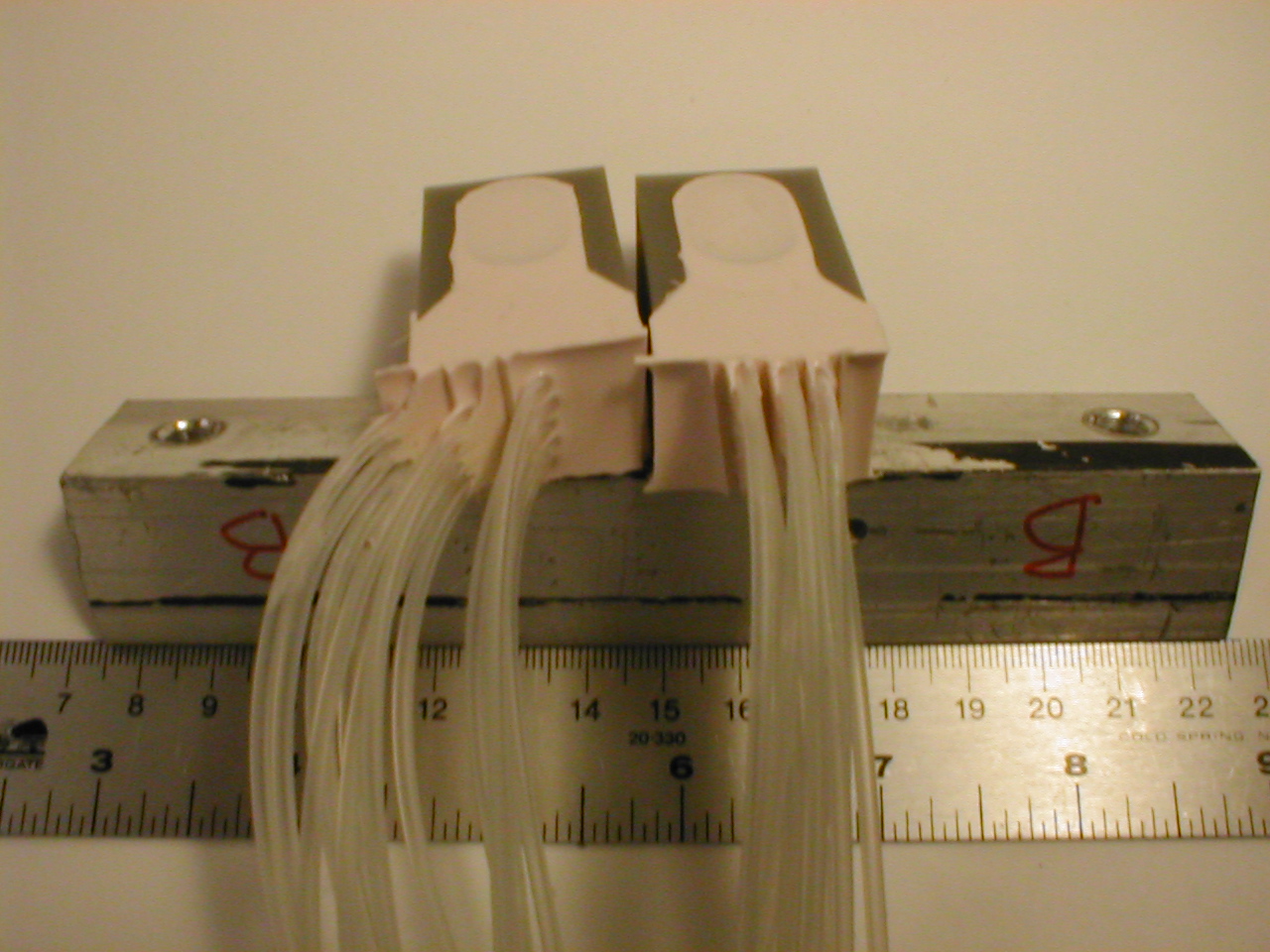
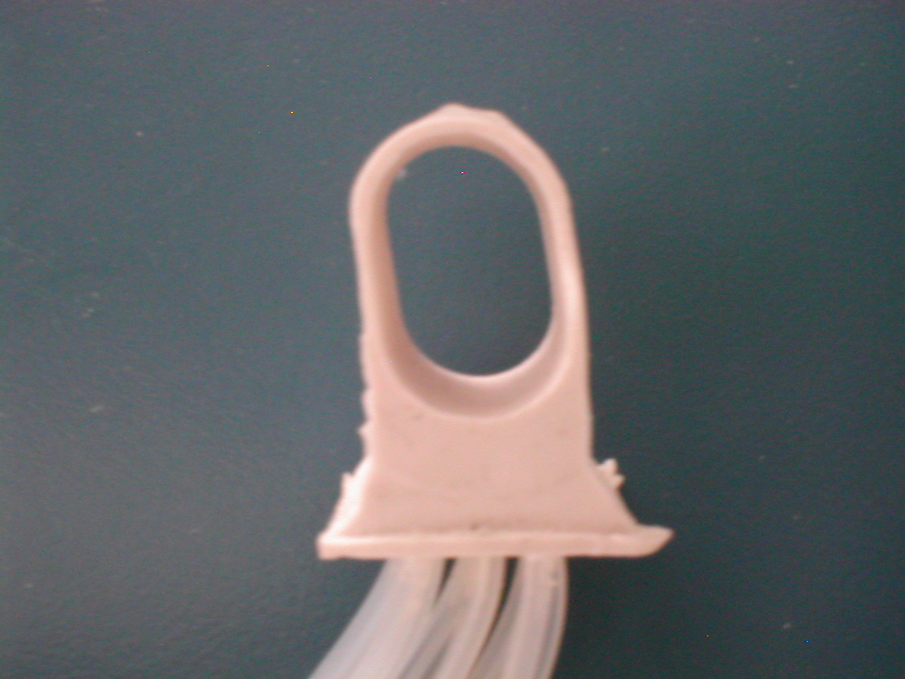
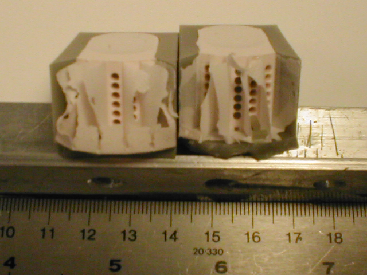
Remove weights and plexiglass plate. Use an X-Acto knife to remove
excess rubber until you get something resembling this picture:
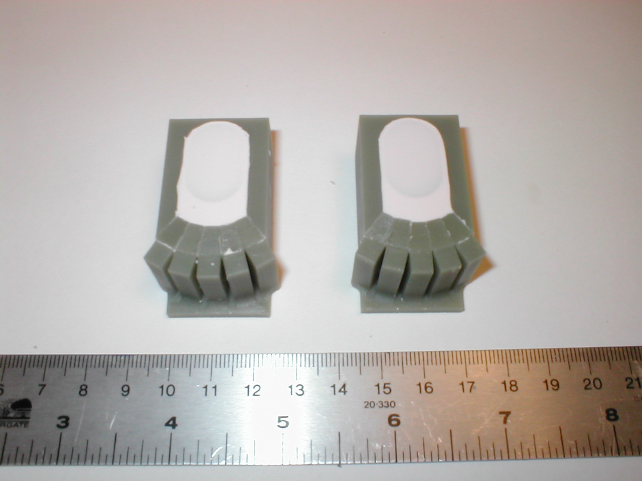
Carefully break off the five support beams behind the pin piece molds.
Slide out the 5 pin pieces. Remove broken pin piece structures left
inside the mold with tweezers. Trim excess rubber with an X-Acto knife.

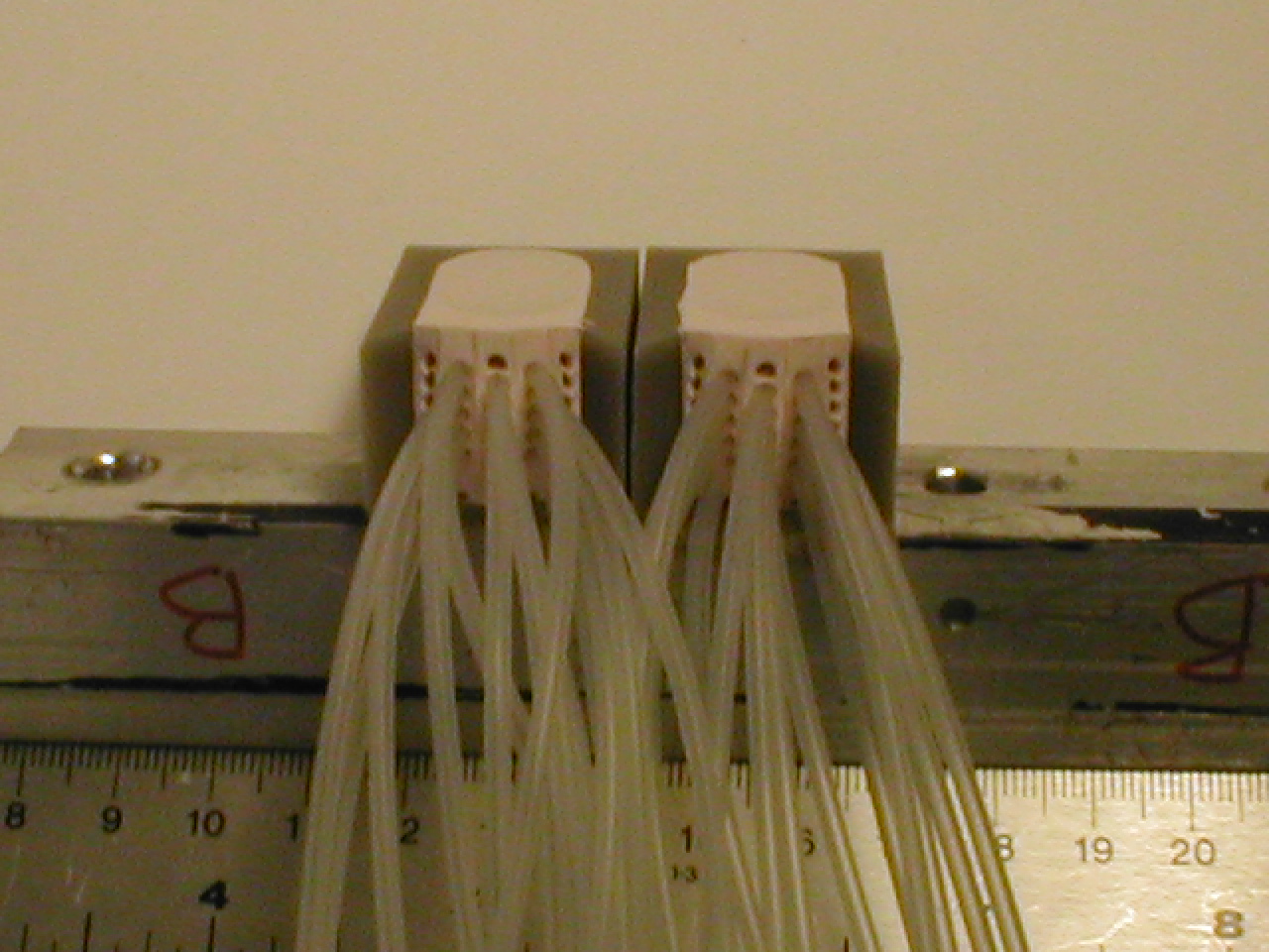
Tube Insertion
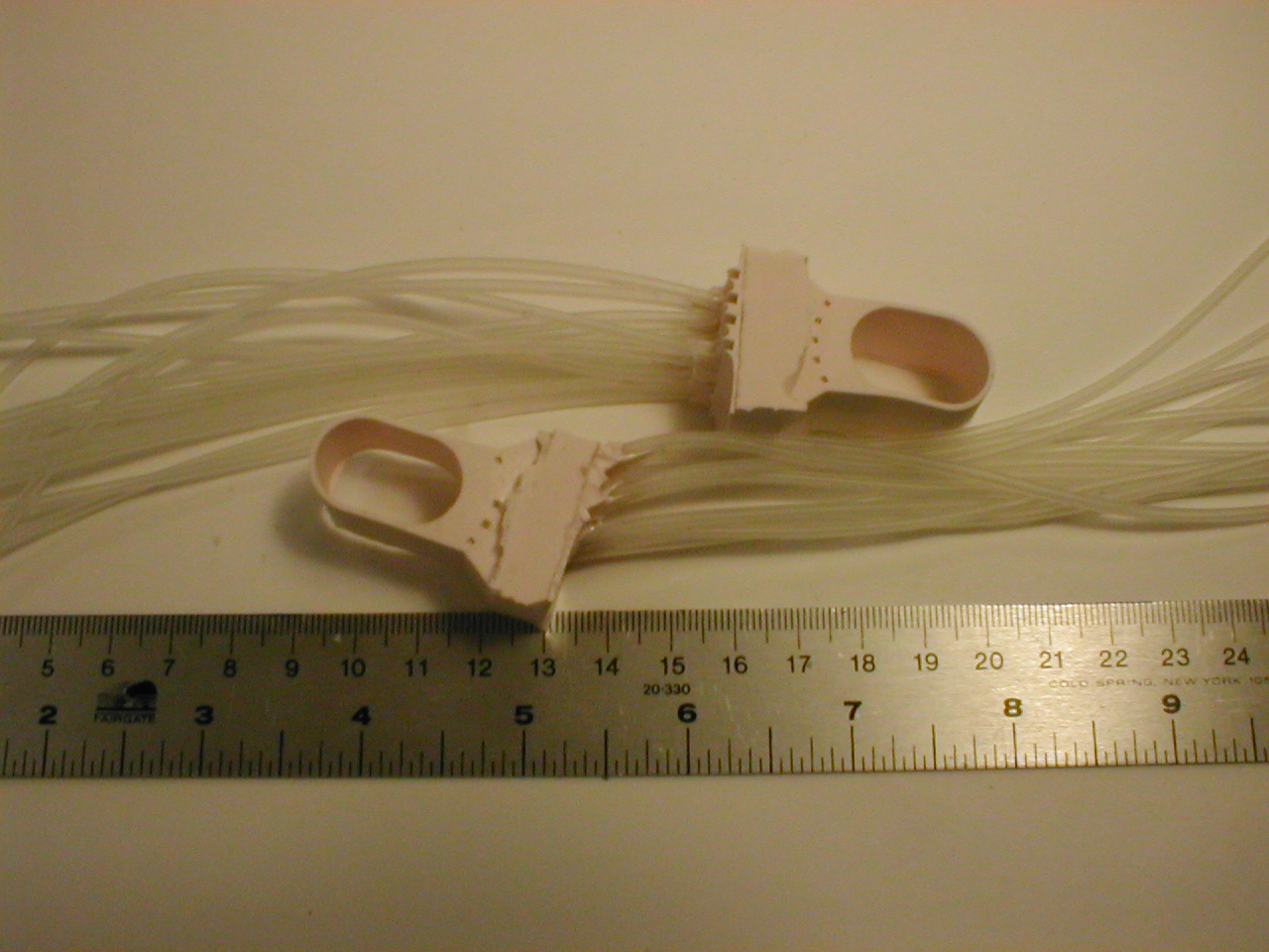
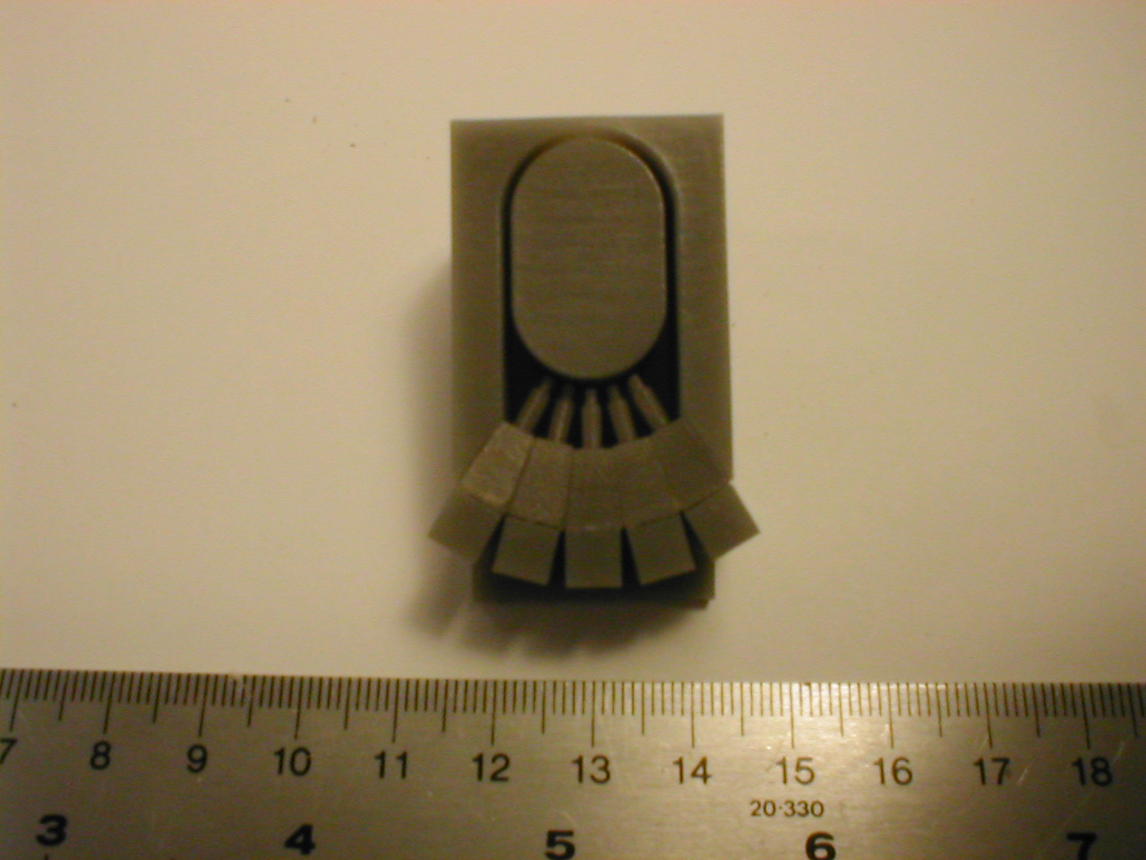
Determine how many elements you want to have in your tactile display.
Cut silicone tubes to the desired length. Push the tubes into the mold.
A 14 element display in a 5-4-5 configuration is shown below.
Final Molding
Determine the final mold shape and carefully place the display and tubes
between two plexiglass plates. Use at least
2 mm of rubber to ensure that the tubes stay attached to the display. Use
other base pieces as separators between the displays, if
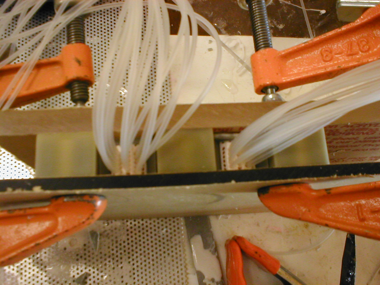
necessary. Mix some HS II and pour in between the tubes. Do not
vacuum the workpieces as HS II might fill the air chambers.
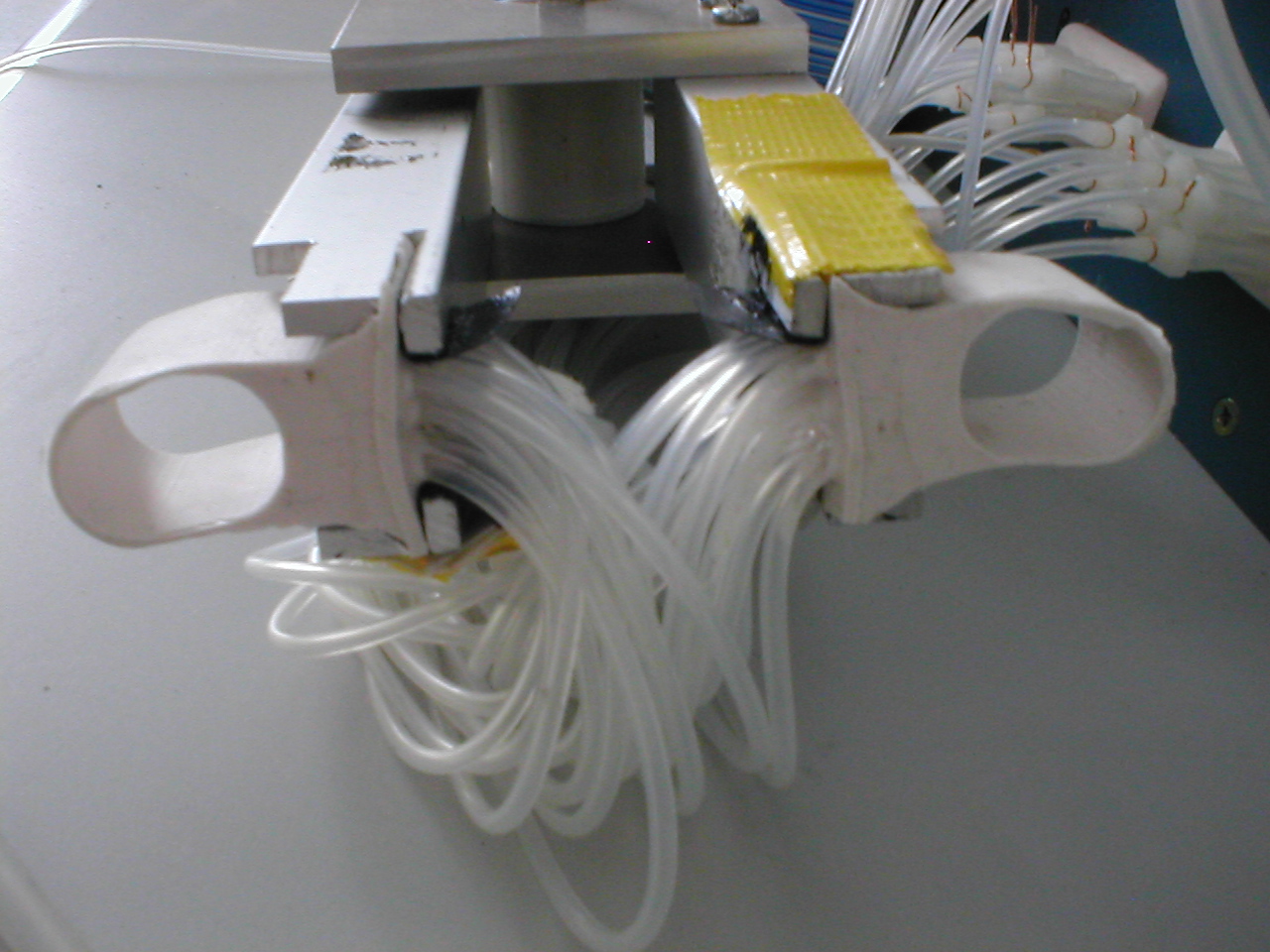
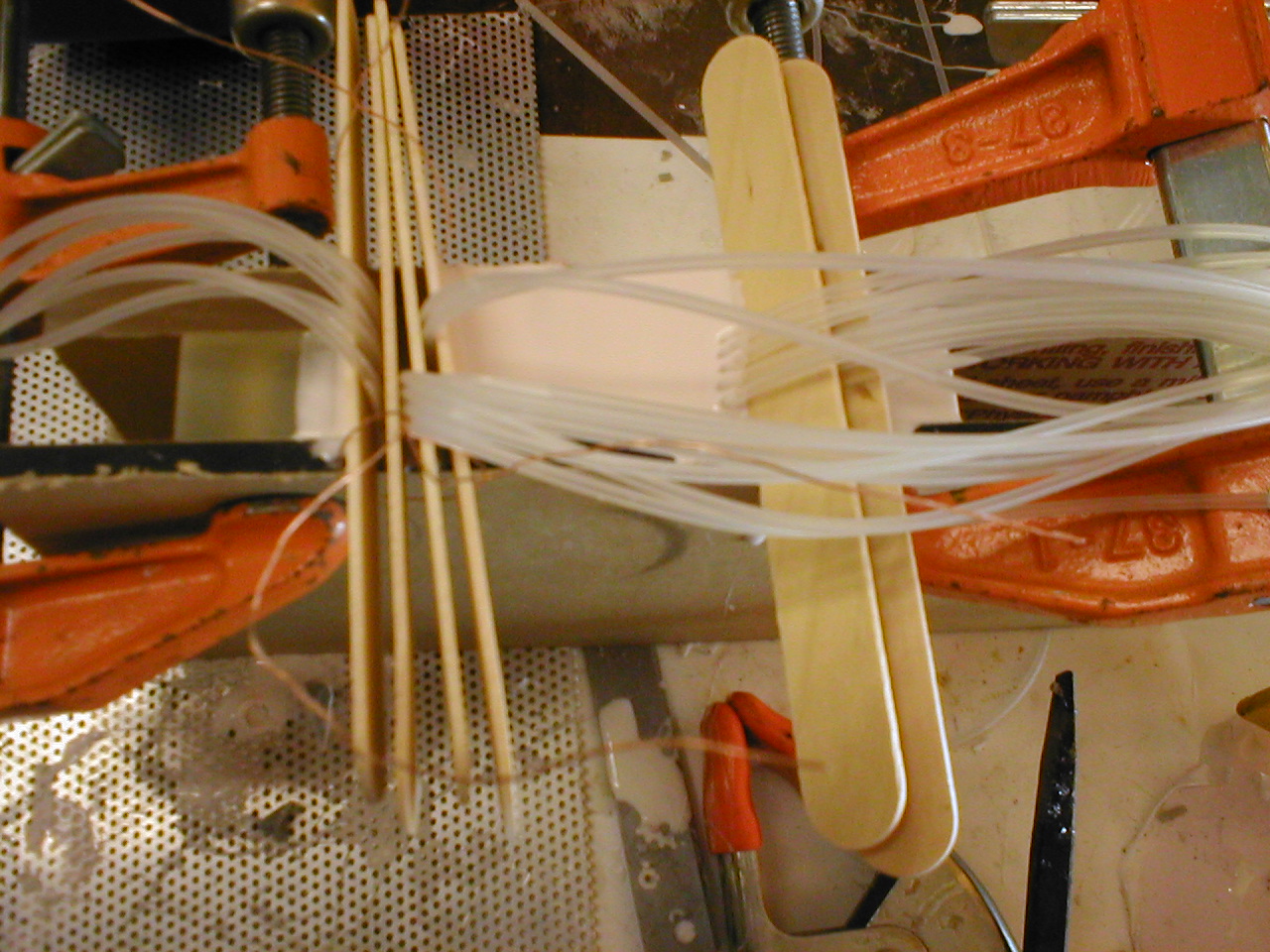
Separate the tubes with tongue depressors as shown below
Let the HS II cure for 24 hours.
Remove the clamps and release the molds from the plexiglass.
Remove the tactile display from the mold and trim excess rubber.