Actuator Design for Pre-stressed PZT with Rigid Extension

last update Mar. 6, 2002.
This actuator provides the high displacement and low stiffness of the 16x3 mm PZT unimorph, but has increased robustness due to pre-stressing with polyimide, improved uniformity due to a spin coated bonding layer, faster fabrication, and higher resonant frequency due to the rigid extension on the 10 mm active PZT length. Finished actuator dimensions: total thickness 222 micron =(138 um piezo + 75 um steel + 5-10 um bond layer)

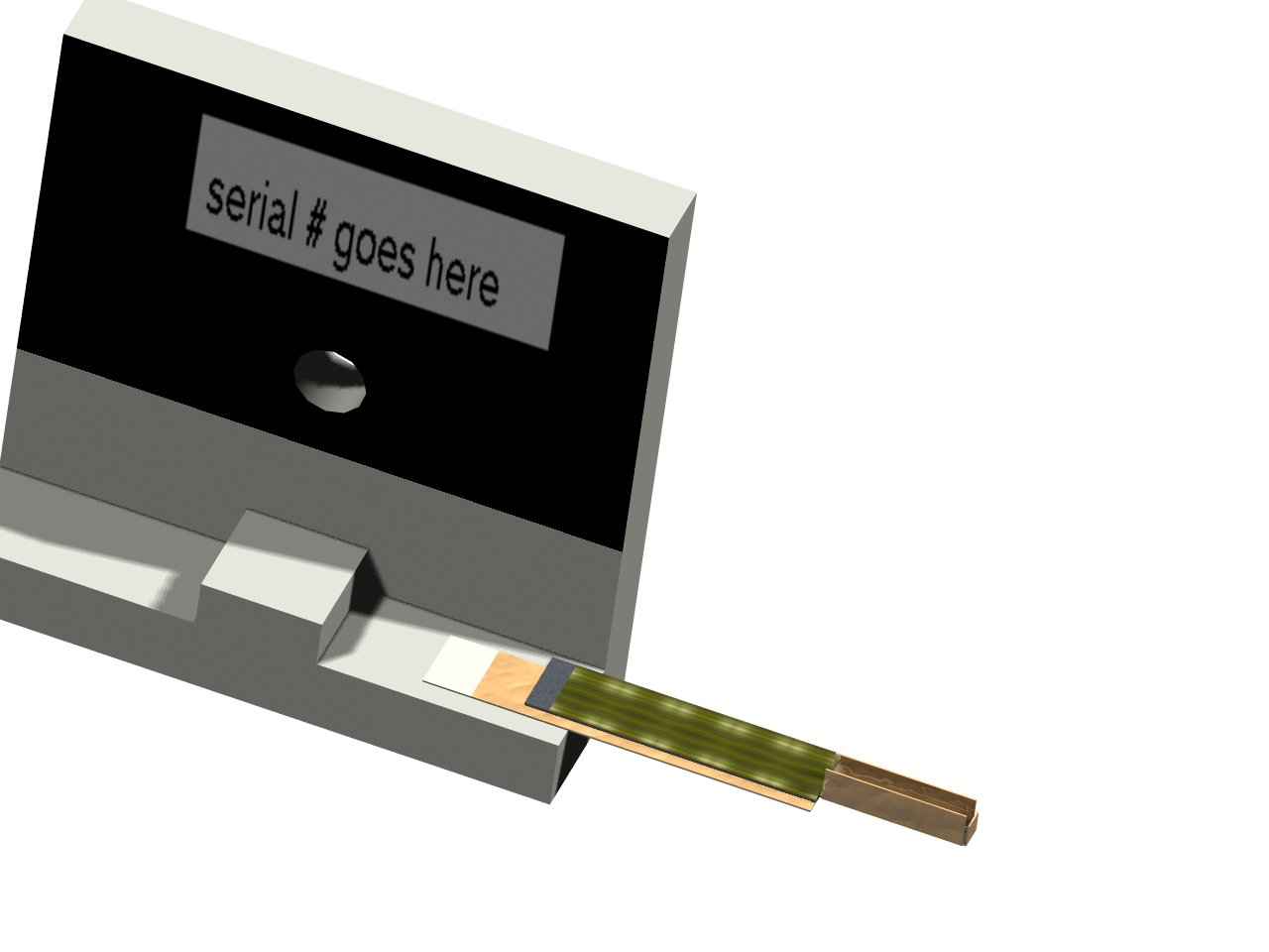
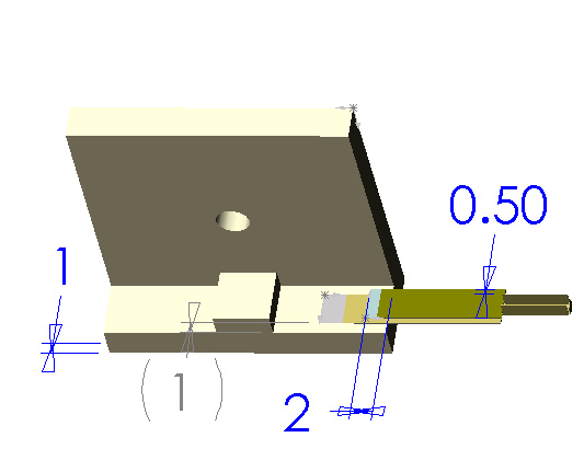
Pre-stressed unimorph with 10 mm active length PZT. Total piezo length 12mm, with 2 mm overhang on mounting block.

Recipe for Prestressed Actuator with Extension (2002/02/02)

Data at 150 volts. Measured Q of 12.
delta Fb fr K (tension)
(micron) (mN) (Hz) ( N/m)
theory 320 49 513 150
1-22-02-01 410 55 500 110
1-22-02-02R 330 51 550 146

1. prepare stainless 3 mil sheet with 3.5 um coating

  • stainless steel sheet on glass slide (water holds ok)
  • spin coat adhesion promotor, spin dry only (100 deg C might be ok)
  • spin coat 2525 polyimide, (spin 50 sec 4 oclock), softbake 200 deg C in vacuum oven for 30 minutes
  • repeat adhesion promotor, 2525, softbake on other side
    2525 is safer since it doesn't need adhesion promoter
  • laser cut 20 x 3 mm polyimide mask, avoid overblast to get clean etched edges. (file is piezo10x3b.dxf or piezo10x3x10.dxf). Laser at 20X green, high power (~600/1000), 80% mask, step 80 um, 10 flash per second
  • etch in fresh FeCl3 on hotplate (#3) with stirrer until all the way through (10-15 minutes). Check every 3 minutes to avoid over-etch.
  • rinse well in water
  • measure and record plate thickness
  • separate plates with Xacto knife
  • scrape polyimide from one long edge on backside (with rough edges) to use for electrical contact to piezo

    2. prepare 12x3 PZT

  • cut PZT sheet (measure and record thickness)
  • mask back side edge and top base edge with scotch tape (or with enamel paint so can remove with acetone) (May not be necessary if piezo is neatly placed on wet polyimide.)
  • (spin coat adhesion promoter if using 2611)

    3. bond piezo with polyimide (2611 has lower residual stress than 2525)

    Use 2525 to avoid bonding problems
  • place 20x3 mm stainless on gelpak, smooth side up
  • spin coat 2525, timer 1, 18 sec, 2 oclock, timer 2: 30 sec at 3 oclock (make sure 2525 covers whole steel piece before spinning)
  • carefully place PZT on top of stainless, align, gently press down. Piezo should be offset 0.5 mm from side edge of stainless, and flush with start of U channel (don't overlap bend area.) Don't slide around or edge of piezo may get covered in polyimide.
  • place SS+PZT on gelpak on warmed hotplate at #3 to partially cure polyimide, 2-5 minutes (?)
  • spin coat 2525 on top of PZT (same as above), except spin #2 at 2 oclock
  • hotplate #3 to partially cure polyimide (2-5 minutes)
  • remove from gelpak
  • remove scotch tape masks or paint mask, excess blobs of polyimide
  • sandwich between glass slides to prevent stressing before polyimide cures. Polyimide should be already cured enough so it won't stick to glass.
  • softbake in vacuum oven 200 C > 30 minutes (or hotplate #6)
  • (use laser on 20X green to remove polyimide from stainless and piezo electrical contact areas.) mask is quicker.
  • Keep actuator sandwiched between glass while heating until polyimide is fully cured. Ramp temperature up to prevent bubble formation. Hardbake on hotplate #9 > 30 minutes. Degree of pre-stress depends on how quickly actuator is cooled. When cooled, actuator should be bent/pre-stressed.
  • measure and record actuator total thickness to verify bond layer thickness and uniformity.
  • carefully cut polyimide between piezo and U channel, then carefully bend end flap and U channel up using pliers and moment applied by razor blade.

    4. Holder and Wires

  • strip and tin with solder each end of a pair of solid copper wires, attach other end to .156in connector
  • carefully scrape polyimide off stainless at base area, then use aluminum flux to solder wire to stainless steel
  • tack actuator in place using super glue. Piezo should extend 2 mm before edge of polyurethane holder to ensure strong base connection.
  • weld wires to polyurethane base using soldering iron
  • use conductive epoxy to connect back side SS with back side piezo
  • use conductive epoxy to attach plus lead to top piezo
  • attach actuator base to polyurethane base using two hour epoxy, also reinforce L/U beam connection at end of piezo with 2 hour epoxy
  • cure conductive and 2 hour epoxy for 30 minutes at 100 C in vacuum oven
  • optional- use 2 hour epoxy to coat conductive epoxy and hold wires more firmly in place, cure for 30 minutes at 100 C in vacuum oven
    5. Testing and Break In
  • Pole actuator at 400 V for 5 minutes.
  • Record displacement at 150 V, stiffness, blocked force, resonant frequency (at 12 v p-p). Check that actuator performance meets specs.
  • Run at resonance (should be near 500 Hz) with 1 mm p-p motion for 1-2 hours. If parameters (such as resonant frequency) shift, a crack has developed and actuator should be set in to-be-repaired pile.
  • Functioning actuators can be gauged, retested, then removed if needed to be used on flightmill structures.