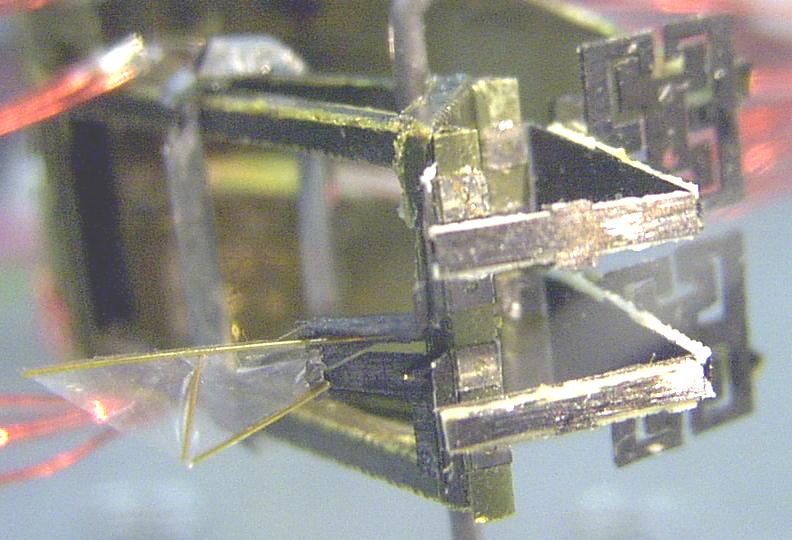
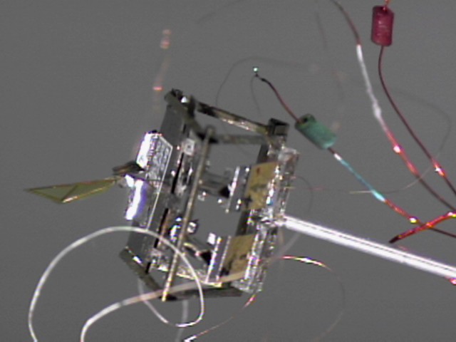
Aug. 2002
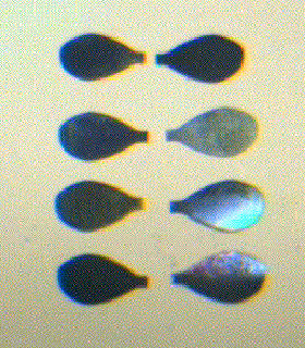
(left) 02lambda one wing flapper, 160 Hz resonant frequency.
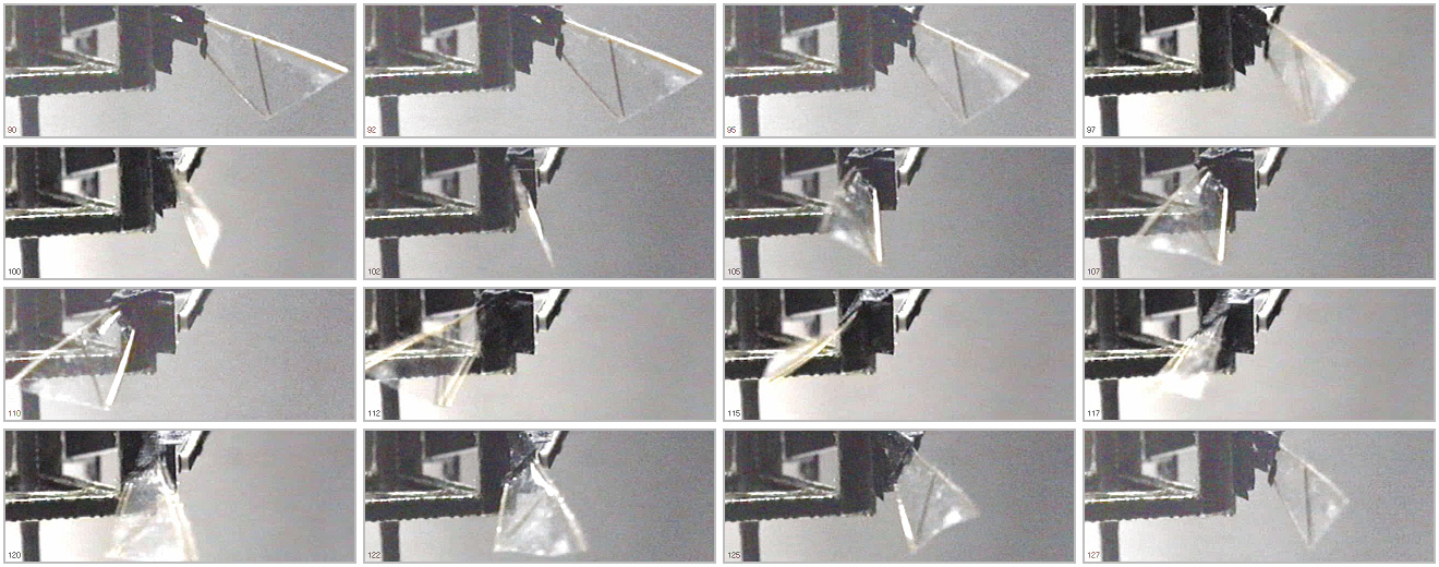
(right) Wing stroke sequence at 160 Hz.
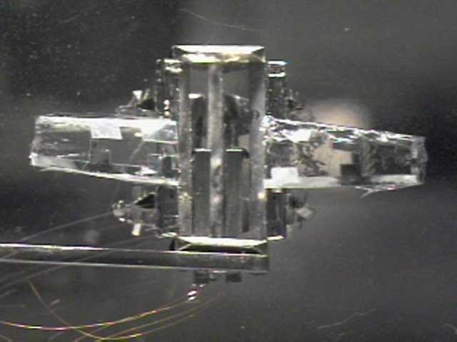
Aug. 2001
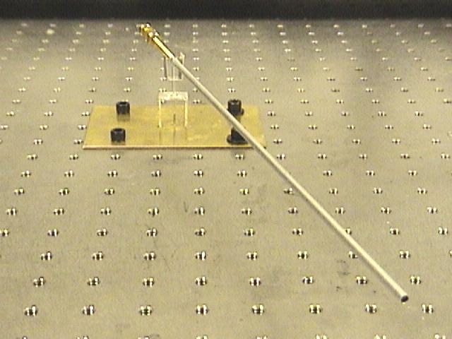
(left) Flight mill for constrained flight testing with 2 degrees of freedom.
(right) One wing flapper (with oversize frame) attached to flight mill.
Mar. 2001
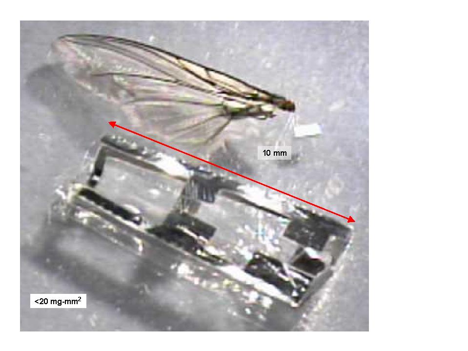

(left) Wing constructed from 6 micron polyester frame with 2 micron face-sheet,
with Calliphora wing.
(right) Model of wing drive kinematics.
Structural integration test bed with 5x1 mm PZN-PT actuators,
and two 1 DOF wings.
(Missing wing differential).
Dec. 2000
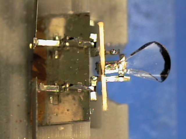
(left) Two DOF thorax driven by pair of 16x3 PZT unimorphs, with 1 cm wing.
(right) Flapping and rotation at 40 Hz.
May. 2000
1.4X stainless steel thorax driven with PZT unimorph at low amplitude.
Mar. 2000
1.4X stainless steel thorax with polyester wings and flexural joints.
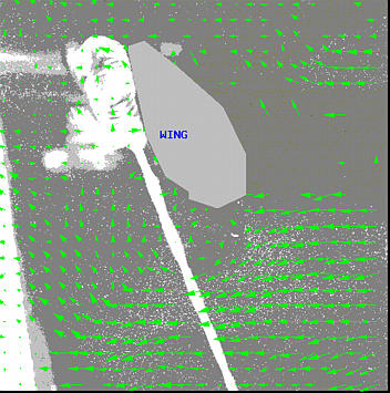
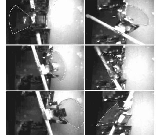
Sept. 1999
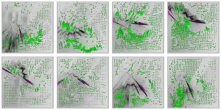
5X polyester fanfold wing structure beating at 17 Hz in wind tunnel. Complete stroke shown starting at bottom of stroke, upper left. Dark line is laser light sheet.
Aug. 1999
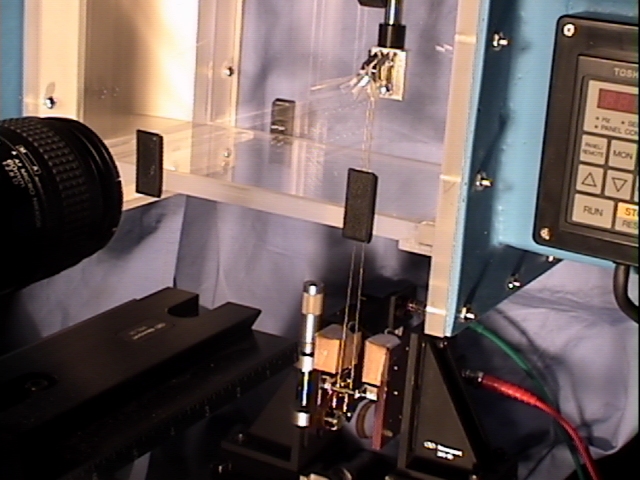
Large-scale fan-fold wing driven by voice coil actuators mounted in
wind tunnel for particle image velocimetry measurements.
Stainless steel thorax structure with polyester wing.
Ken Chiang has started design of a conventionally actuated mockup of an insect to explore wing stroke kinematics and control. The wings will be approximately 10 mm in size and driven by push rods using voice-coil actuators. We have some preliminary flow images with low wing velocity. Flow Image
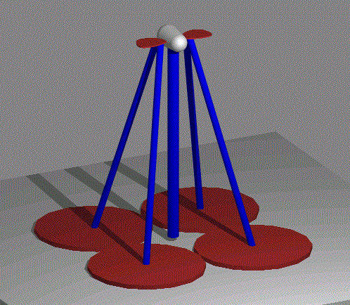
Wing drive system with 2 DOF per wing.
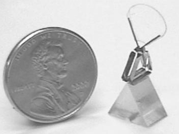
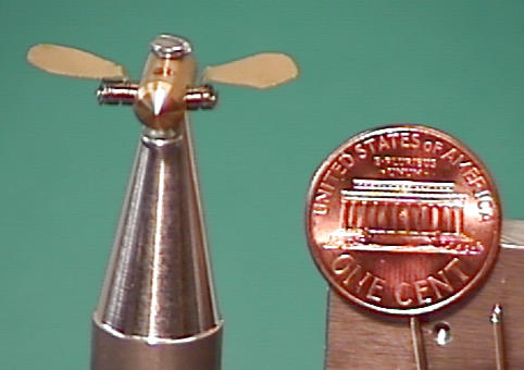
Preliminary version of steel wings, 10 mm in length, 100 micron thick made
using EDM process.
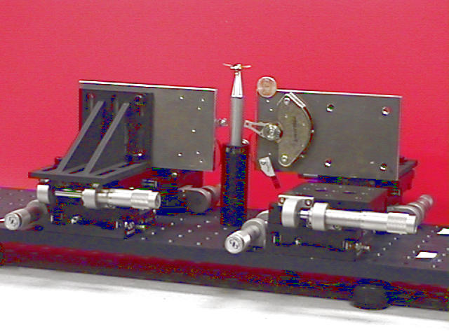
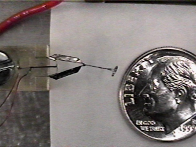
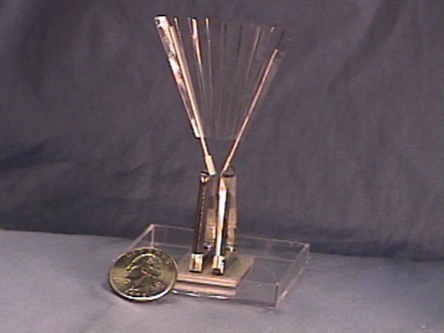
Drive system for wing mockup using voice coil actuators.
Positioning stages are used to easily change
actuator attachment direction and pre-loading. For clarity,
only 2 of 4 actuators are installed. Insect body and wings
are barely visible to left of penny.
Wings attached to mockup body using springs.
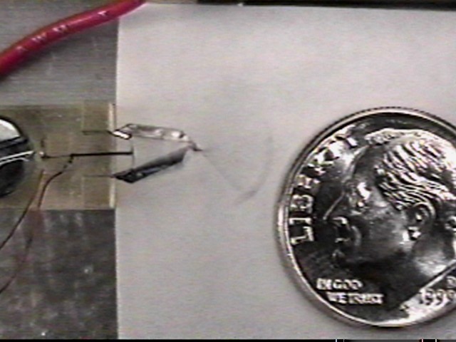
Flow image with wing driven at 30 Hz, stroke amplitude 45 degrees. Approximate peak wing tip speed of 1 m/s. Particle seeding is from right side of image. Hints of vortex formation at the wing tip can be seen. Wing drive using servo amp will be at 80 Hz and stroke amplitude greater than 90 degrees, and should give at least an order of magnitude greater fluid force.