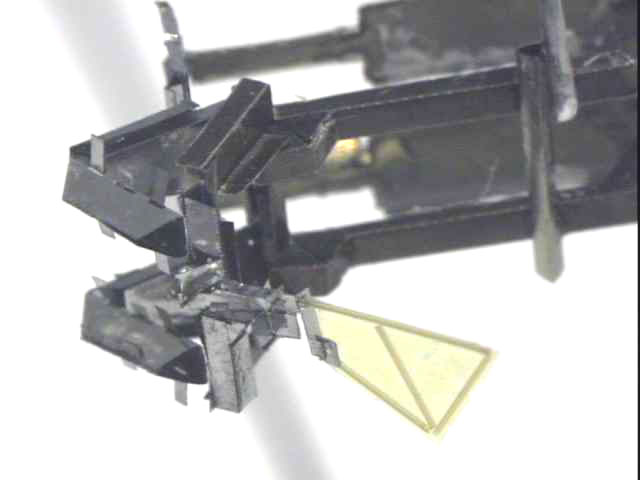
Close up of the wing differential on 02-γ
|
Close up of the wing differential on 02-γ |
|
Fourbar Dimensions See solidworks drawings for complete dimensions. |
Link lengths (mm) | 6, 6, 6, 1 |
| Flexure lengths (μm) | 50, 50, 112.5, 112.5 | |
| Flexure widths (mm) | 3,2,2,2.5 | |
| Slider crank dimensions | Attachment point (mm) | 1.5 |
|
Wing Differential Dimensions See solidworks drawings for complete dimensions. |
Leading and lagging spar lengths (mm) | 2,3 |
| Leading and lagging spar inertias (mg-mm^2) | 2,3 | |
| Distance between spars (mm) | 1 | |
| Differential Transmission ratio | 2 | |
| Inertia of middle portion of differential (mg-mm^2) | md1 = 4.4, md2 = 0.37, md12 = 1.02 | |
| Flexure lengths (μm) | l_ψ = l_ θ3 = 175. l_φ = l_θ1 = l_θ2 = 50 |
|
| Flexure widths (mm) |
w_ψ = w_θ1 = w_θ2 = w_ θ3 = 1 w_φ = 2 |
|
| Actuator parameters | Dimensions (mm) | (10 + 6) x 3 |
| Serial Numbers | 02-27-02-01M, 02-27-02-05M | |
| DC displacements (μm @ 150V) | 315, 337 | |
| Stiffneses (N/m) | 122, 122 | |
| Blocking force (mN @ 150V) | 43, 43 | |
| Resonant Frequency (Hz) | 621, 529 | |
| Q (= Xac/Xdc*150/Vac) | 18.6, 21.76 |