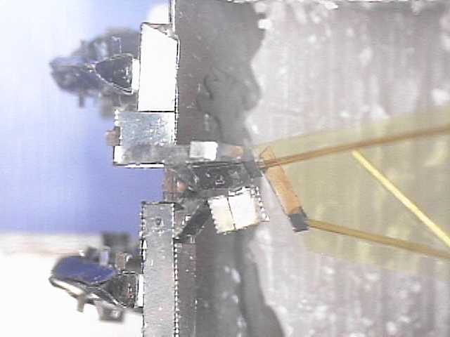
Close up of the wing differential on 01η
 Close up of the wing differential on 01η |
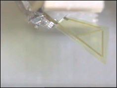
Another important advance in this generation was to use polyimide wings. This method enables the fabrication of very light, stiff wings with very accurate inertias which was found to be very critical for getting the right response. For the first time, we had a wing which has the same inertia as a calliphora wing.
Salient Features

Actuator Parameters
Two matched 16 x 3 PZT-5H actuators were used.
- Blocking Force: 85 mN @ 200V
- DC deflection (unloaded): 750 microns @ 200V
- Actuator inertia reflected onto wing hinge: 3.3 mg-mm^2 (each)
- Actuator stiffness reflected onto wing hinge: 0.95e-6 Nm/rad (each)
Fourbar Parameters
- slider crank attachment point : 2 mm.
- fourbar dimensions : 6, 6, 6, 1 mm.
- Fourbar inertia reflected onto wing hinge: 1.7 mg-mm^2 (each)
- fourbar parallel stiffness: (not measured, theoretically < 1/10 actuator stiffness)
Differential Parameters
- 6.25 micron polyester flexures (for all joints including in slider crank).
- differential transmission ratio: λ = 2
- size of differential:
1. length of leading spar : 3 mm, inertia = 3 mg-mm^2
2. length of lagging spar : 2 mm, inertia = 2 mg-mm^2
- Length of flexures: (l_ψ = l_θ3 = 175 microns. all other flexures 50 microns each.)
- Mean differential Stiffness: 0.47e-6 Nm/rad (about 1/2 of actuator stiffness)
- Inertia of "middle" portion of differnetial:
md1 = 4.4, md2 = 0.37, md12 = 1.02 (mg-mm^2)
Wing Parameters
- Wing Inertias
Jxx = 21.1505, Jxz = 5.6836, Jzz = 2.2875 (mg-mm^2)
where 'x' is the flapping direction and 'z' is the rotation direction. This inertia distribution was acheived after offsetting the original wing by 0.5 mm in the rotational direction. The wing was made using the new polyimide recipe. Face sheet thickness = 7 microns, tube dia = 200 microns. weight = 0.48 mg. inertia = 21 mg-mm^2.- Self resonance: ~ 350 Hz
- Nominal frequency response from torques to spar angles:
First Resonance at 105.5532 Hz
Second Resonance at 160.455 Hz
Note that the coupling exhibited is much larger than for a larger damping. The prediction above is for small amplitudes where Q ~ 4.5- Nominal frequency response predicted for strain gage measurements (the frequency response from voltage inputs to strain gage signals):
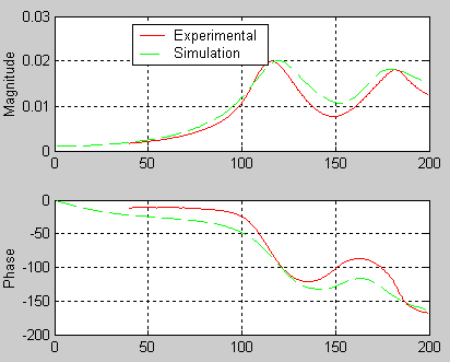
First Resonance at 120.314 Hz
Second Resonance at 180.478 Hz
- Resonant Frequencies (from Mimmo's data)
First resonance at 105 Hz
Second resonance at 160 Hz
- Resonant Frequencies (from Rob's measurements)
First resonance at 115 Hz
Second resonance at 180 Hz
(the difference between the observed resonances can be theoretically explained by accounting for the strain gage setup dynamics)- Q: about 2.5 for large amplitudes (120+ V) and about 4.5 for smaller amplitudes (18 V)
- DC motion: ~40 degrees for 150V
- Theoretical and Measured Frequency response of strain gage signal:

From Vinput_lead -> Vsense_lead
From Vinput_lead -> Vsense_trail
- Theoretical and Experimental Frequency responses from Mimmo's measurements:
Note that only the 1-1 measurement was made.