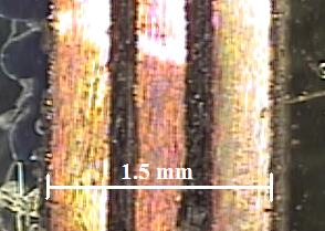
Close-up of wiring ribbon cable
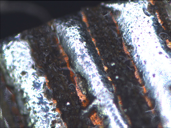
Close-up of the ribbon cable tinned with low melting point solder
Step 1: Pattern copper (or gold) foil that is attached to non sticky back Gel-pak 8 with the laser. We, for instance, pattern the copper foil such that we have three wires that are each 400 µm wide with 150 µm spacing between them.
Step 2: Remove excess foil and spin coat a thin layer of polyimide (PI 2525) on the patterned foil.
Step 3: Place a sheet of 7 micron thick Kapton® over the spin coated polyimide.
Step 4: Heat on a 300 deg C hotplate for 5 minutes. Remove the Gel-pak and heat wiring with Kapton® backing for a remaining 20 to 25 minutes.
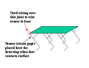
The
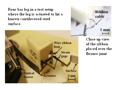
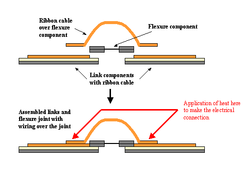
wiring ribbon cable is included on the link elements. Where
necessary, a loop of ribbon cable is placed over the joints.
The electrical connection is made through the use of low melting point solder (e.g. TIX soft solder). The ends of the ribbon cable on the link elements as well as the ends of the loops of ribbon cable placed over the flexure joints are tinned with the low melting point solder.
An application of heat (for example, with a soldering iron) on the ribbon cable ends where it overlaps between the flexure joints and links will electrically connect the two together.