Stainless
Steel and
Polyester
Kit Parts
Stainless Steel Faceplate
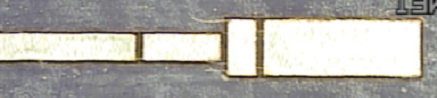
Step 1: 12.5 micron steel should be placed on Gel-pak 4
that is adheared to a glass slide.
Step 2: Cut out the desired pattern with a
laser.
Step 3: The excess steel can then be peeled away leaving just the
faceplate.
Polyester Flexures
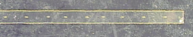
Step 1: Cut a small square of polyester of the desired
thickness (e.g. 6 or 12 microns) and place it on Gel-pak 4 that is
mounted on a glass
slide.
Step 2: Cut out the polyester flexure 1mm wide and to the desired
length using the laser.
Alternatively, you can cut out long strips of the poyester with the
laser and store it for future use. When needed, it can then be
cut to
desired length.
Stainless Steel Beams
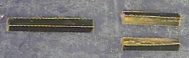
Step 1: 12.5 micron steel should be placed on Gel-Pak 4 that is
attached to a glass
slide and
polyimide (PI2525) spin coated on it. The polyimide coating
should be soft baked on a hot plate (a minute with the Gel-Pak and then
the steel piece should be removed from the Gel-Pak and cured alone for
about 30 minutes).
Step 2: The appropiate pattern (cut and score lines) can be applied by
the
laser. Then flip the piece over and spin coat polyimide on the
opposite side the same way as described above.
Step 3: Etch the piece. (This can be done by placing the steel in
a
beaker and pouring a small layer of ferric chloride on top. Then
place the beaker on a hot plate with a magnetic stirrer under a
hood. It is usually finished in a 5 minutes or less depending on
the side of the piece.)
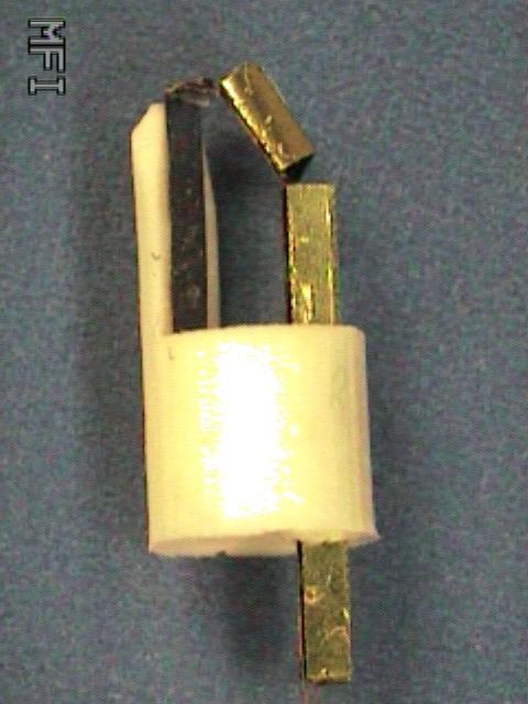
Step 4: The piece can then placed on the folding fixture and
folded. Seal it in place by applying superglue with a thin needle
and running the triangle through a triangular channel. Cut off
the beam and repeat the folding and gluing process for as many beams
that were patterned.
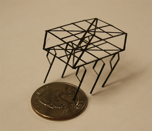
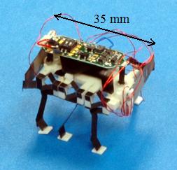
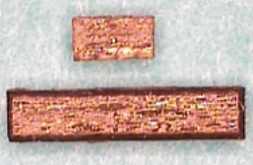
Example Structure Built from these Kit
Parts
Carbon
Fiber and Polyester Kit Parts
Carbon Fiber Links
Step 1: The uncured carbon fiber can be cut into strips and
stored in
the
freezer until it is ready to be used.
Flexure Elements
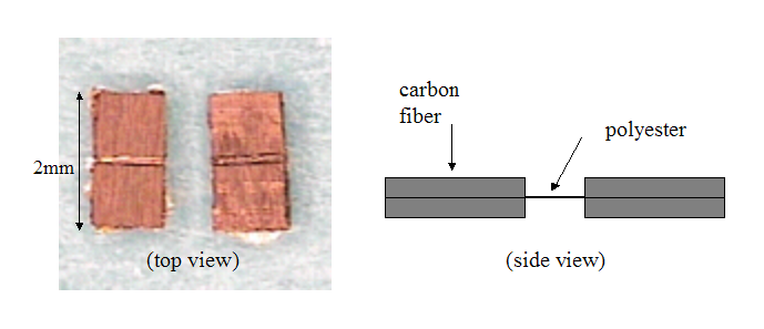
Step 1: A carbon fiber layer can be patterned into flexure
elements
under the
laser.
Step 2: Place a layer of polyester on top of the patterned carbon
fiber
layer. Place a teflon layer on top and then a glass slide.
Step 3: Put the assembly in a 150 deg C vacuum
oven with a weight on top to be cured.
Step 4: The same pattern should
then be applied to another carbon fiber layer using the laser.
Step 5: Place the cured polyester and
carbon fiber layer on top of the newly patterned carbon fiber so that
the polyester is in between
the two carbon fiber layers.
Step 6: The whole structure should be cured
in the oven in the same fashion as described in Step 3. When it
is
finished, the individual flexure elements can then be separated easily
with a razor blade.
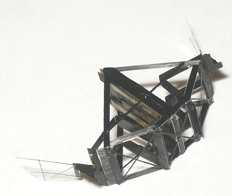
Example Structures Built from Carbon
Fiber/Polyester Combination