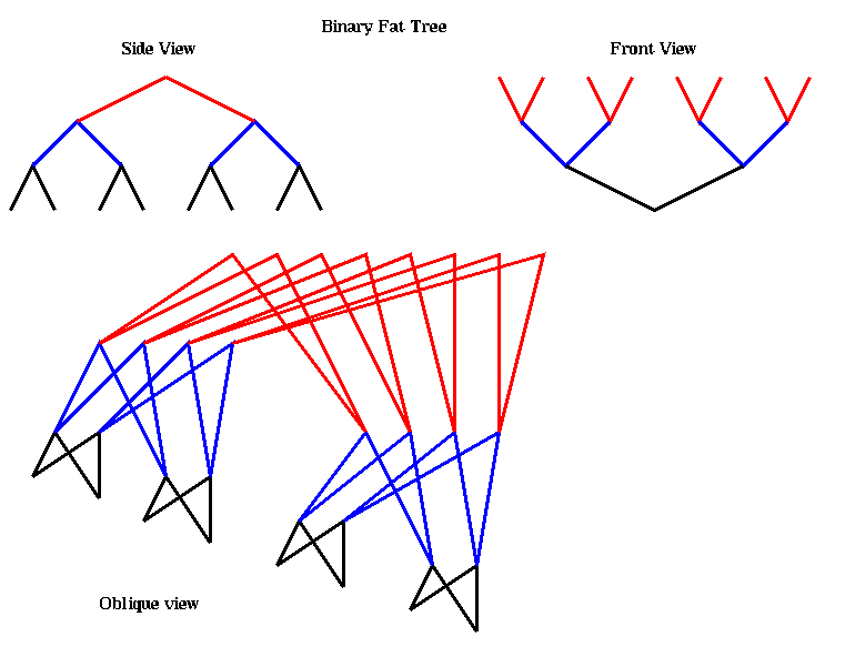
A message is routed from processor i to processor j as follows. All the processors are at the leaves (the bottom), and the other nodes are routing processors. Starting from processor i, a message moves up the tree along the unique path taking it to the first possible common ancestor of i and j in the tree. There are many possible paths (a choice of two at each routing processor), so the routing processor chooses one at random in order to balance the load in the network. Upon reaching this first common ancestor, the message is then routed back down along the unique path connecting it to j. The diameter of this network is 2 log_2 p, and the bisection width is p/2
It is possible to have non-binary fat tree; the CM-5 uses a 4-way tree. It is also unnecessary to double the number of wires at each level; the CM-5 save some wires (and so cost) by having fewer wires at the top of the tree. The resulting maximum bandwidths are:
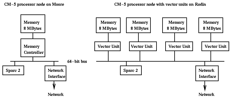
   Among  4 nearest processors:  20 MBytes/sec
   Among 16 nearest processors:  10 MBytes/sec
   Among remaining  processors:   5 MBytes/sec
Some of this bandwidth is used up in message headers, as mentioned below. Here is a little more detail on the CM-5 data network. The vector units perform fast floating point operations, up to 32 Mflops per unit, for a total of 128 Mflops per node. CMF will automatically generate code using the vector units. To use the vector units from Split-C, one can call the CM-5 numerical library CMSSL (click here for details). The local memory hierarchy on a CM-5 node with vector units is rather complicated, and it turns out that data to be operated on by the vector units must be copied from the memory Split-C data resides in to the segment accessible by the vector units. This copying is done at the speed of the much slower Sparc 2 chip. Unless the CMSSL operation is complicated enough, the copy time may overwhelm the time to do the operation. For example, matrix-matrix multiplication takes O(n^3) flops so copying O(n^2) data is probably well worth it. But matrix-vector multiplication takes only O(n^2) flops and so is not worth using the vector units. The difficulty of using the vector units was a major problem in using the CM-5 effectively, and future architectures are unlikely to mimic it. In particular, the fastest microprocessors have floating point integrated on the same chip as the rest of the CPU and (level 1) cache.
To send a message a processor does the following 3 steps:
To receive a message, a processor uses the following three stepsNote that there is no place in the message for a process ID, to distinguish message from different user processes. This means the machine does not support multiprogramming. It is, however, time-shared, which means the entire data network must be flushed and restored on a context switch ("all fall down" mode).
To prevent deadlock, processors must receive as many messages as they send, to keep the network from backing up. When using CMMD, interrupts are used, so if one has posted an asynchronous receive in anticipation of a message arriving, the processor will be interrupted on arrival, the receive performed, and user-specified handler called (if any). With Split-C, the default is to have interrupts turned off, so it is necessary to poll, or "touch" the network interface periodically to let it have some processor cycles in order to handle pending messages. This is done automatically whenever one does communication. For example at every "global := local" the network will be checked for incoming messages. If one does no communication for a long time, the possibility exists that message will back up and the machine will hang. This is unlikely in a program which does communication on a periodic basis, but nonetheless calling splitc_poll() will "check the mailbox", just in case. (Interrupts can be turned off or on in CMMD with CMMD_{disable,enable}_interrupts, and polling done with CMMD_poll().)
Routing messages may be done by following the edges of the hypercube in paths defined by binary reflected Gray Code. A d-bit Gray Code is a permutation of the integers from 0 to 2^d-1 such that adjacent integers in the list (as well as the first and last) differ by only one bit in their binary expansions. This makes them nearest neighbors in the hypercube. On way to construct such a list is recursively. Let
G(1) = { 0, 1 }
be the 1-bit Gray code. Given the d-bit Gray code
G(d) = { g(0), g(1), ... , g(2^d-1) } ,
the d+1-bit code G(d+1) is defined as
G(d+1) = { 0g(0), 0g(1), ... , 0g(2^d-1), 1g(2^d-1), ... , 1g(1), 1g(0) }
Clearly, if g(i) and g(i+1) differ by one bit, so do the bit patterns in
G(d+1). For example,
G(3) = { 000, 001, 011, 010, 110, 111, 101, 100 }
We will return to Gray codes below when we discuss collective
communication.
Since there are many more wires in a hypercube than either a tree or mesh,
it is possible to embed any of these simpler networks
in a hypercube, and do anything these simpler networks do.
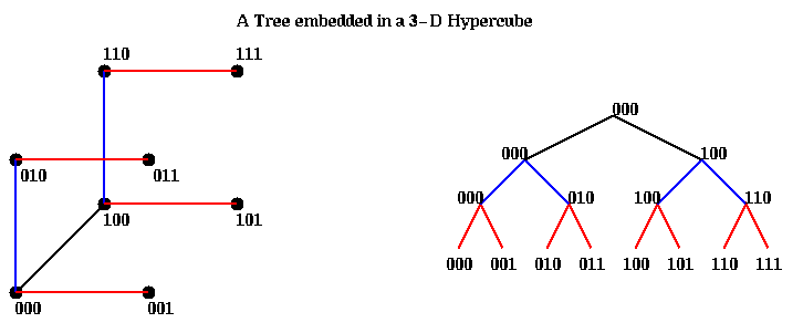
For example, a tree is easy to embed as follows. Suppose there are 8=p=2^d=2^3
processors, and that processor 000 is the root. The children of the
root are gotten by toggling the first address bit, and so are
000 and 100 (so 000 doubles as root and left child). The children
of the children are gotten by toggling the next address bit, and so
are 000, 010, 100 and 110. Note that each node also plays the role of
the left child. Finally, the leaves are gotten by toggling the third bit.
Having one child identified with the parent causes no problems as long
as algorithms use just one row of the tree at a time. Here is a picture.
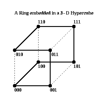
Rings are even easier, since the Gray Code describes exactly the order in
which the adjacent processors in the ring are embedded.
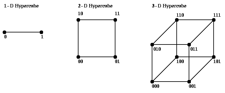
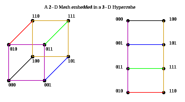
In addition to rings, meshes of any dimension may be embedded in a
hypercube, so that nearest neighbors in the mesh are nearest neighbors
in a hypercube. The restriction is that mesh dimensions must be powers of 2,
and that you need a hypercube of dimension M = m1 + m2 + ... + mk to
embed a 2^m1 x 2^m2 x ... x 2^ mk mesh. We illustrate below by embedding
a 2x4 mesh in a 3-D hypercube:
This connection was used in the early series of Intel Hypercubes, and in the CM-2.
    y0   = x0
    y1   = x0 + x1
    y2   = x0 + x1 + x2
    ...
    yp-1 = x0 + x1 + x2 + ... + xp-1
In what follows, the + operator could be replaced by any other associative
operator (product, max, min, matrix multiplication, ...) but for simplicity
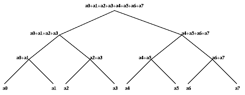
we discuss addition. We show how to compute y0 through yp-1 in 2*log_2 p -1
steps using a tree.
There are two ways to see the pattern. Perhaps the simplest is the
following, where we use the abbreviation i:j, where i <= j, to mean the
sum ai+...+aj. The final values at each node are indicated in blue.
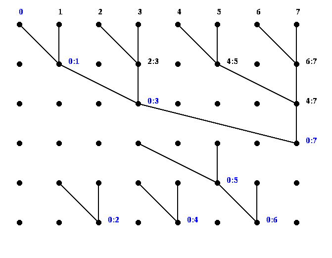
This is actually mapped onto a tree as follows. There is an "up-the-tree" phase, and a "down-the-tree" phase. On the way up, each internal tree node runs the following algorithm.
On the way down, this is the algorithm: On the way up, one can show by induction on the tree that M contains the sum of the leaves of the left subtree at each node. On the way down, one can show by induction that the value T obtained from the parent is the sum of all the leaf nodes to the left of the subtree rooted at the parent. Finally, the value at each leaf is added to the value received from the parent to get the final value. Here is an example.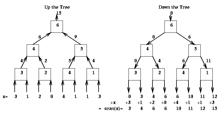
The CM-5 has a second network called the control network, which has a variety of broadcast, reduction and scan operations built into it. Reduction and scan are only supported for logical OR, AND and XOR, as well as signed max, signed integer add, and unsigned integer add. The CM-2 had floating point operations as well, but these were eliminated in the CM-5. It is used by CMMD and Split-C to implement their corresponding high level operations. It performs several other useful operations as well:
Broadcasts, reduction and scans could also be done by the data network, and indeed must be done by the data network for more complicated data types (such as floating point) not handled by the control network.If there are n fish, assign n/p to each processor, and further divide these into d groups of m=n/(p*d) fish. Each group F1,...,Fd of m fish will follow a different path through the node on the algorithm. The first path will be defined by the Gray Code G(d) defined above, the second path will consist of left_circular_shift_by_1(G(d)), i.e. each address in the Gray code will have its bits left shifted circularly by 1; this clearly maintains the Gray code property of having adjacent bit patterns differ in just 1 bit. The i-th path will be left_circular_shift_by_i(G(d)). The student is invited to draw a picture of this communication pattern, which uses "all-the-wires-all-the-time", an interesting feature of the CM-2 hypercube network.