1. Overview
Most IoT applications exchange data and commands with other devices. In same situations, connectivity is local, e.g. for connecting a wireless fitness tracker. Many applications, however, require aggregation of data from many devices and access from users and equipment from many locations.
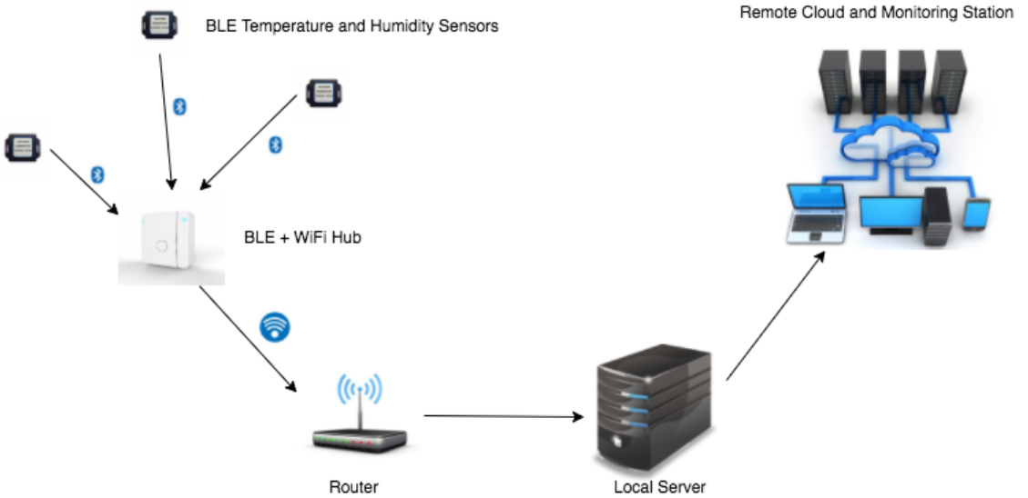
Figure 1 shows a representative IoT applications with IoT nodes (measuring temperature and humidity and this example) relating data to a hub over Bluetooth LE, a low power wireless communication solution. The hub forwards the data over WiFi to a wireless router connected to a local server which sends the data to a “cloud service” (e.g. AWS, IBM, Microsoft) for analysis, archiving, and retrieval by users or machines. In this setup, data or commands can also flow from users to the IoT nodes.
Communication can be wired and wireless. The former is less complex, although an with an increasing number of microcontrollers for IoT incorporating e.g. a WiFi or Bluetooth transceivers, deploying wireless solutions is both becoming easier and less expensive.
Not requiring dedicated wires, which are expensive to install and maintain, is a compelling argument for the wireless approach. However, this benefit comes at the cost of generally lower reliability and reduced security. Susceptibility to interference make it very challenging for wireless solutions to achieve the high availability (greater than 99.999%) of carefully designed wired solutions. Although encryption can be used to secure wireless communication channels, a long list of breaches of supposedly secure protocols such as “Wired Equivalent Privacy (WEP)” suggests that, despite the name, achieving such goals is difficult in practice. By comparison, in a wired solution the attacker needs access to the physical wire which may be easier to protect.
2. Wired Communication
Many options exists for wired communication between IoT devices. GPIO, including serial protocols such as I2C, offers good choices for nearby communication, typically to devices on the same circuit board or in the same enclosure.
Longer communication distances need to deal with signal attenuation and interference e.g. from nearby power wires or other communication signals. For data rates below 10Mbps (Mega-bit per second), the universal asynchronous receiver-transmitter (UART) is a versatile option and supported by most IoT microcontrollers. It uses two wires for bidirectional communication and no separate clock wire. Except for very short distances (e.g. between chips on the same circuit board), the 3.3V UART signals from the microcontroller must be passed though a transceiver chip. Transceivers boost drive strength, enabling higher speed and longer distance, and have circuitry to deal with signal attenuation and corruption in the receiver.
For short communication links, UART signals can be routed over USB or the older RS-232. RS-232 uses 12V for signaling; many vendors offer chips that translate between the 3.3V microcontroller inputs and outputs and RS-232 signals.
Higher performance versions widely used in industrial settings include RS-422 is a higher performance version widely used in industrial settings which works at distances in excess of 1000 meter and data rates up to 10Mbps. RS-485 uses the same signaling as RS-422 but adds multi-drop capability where several devices can time multiplex the same wires.
Ethernet supports direct connection to the internet and even higher data rates up to 1Gbps. It is built-in in some IoT microcontrollers and supported as add-on for others.
3. RF Communication
3.1. Electromagnetic Radiation
Although various approaches exist for wireless communication such as sound, light, or smoke signals, radio frequency electromagnetic radiation is often the preferred approach. Unlike other solutions, RF signals pass through obstacles such as walls, enable multiple simultaneous communications without interfering with each other, and, thanks to microelectronics, can be very small and affordable.
Electromagnetic waves are emitted by electrically charged particles (e.g. electrons) undergoing acceleration. These waves can subsequently interact with other charged particles at (great) distance, exerting force on them.
All of this can be achieved with electronic circuits to generate changing current (accelerating electrons) in a transmitter, and detect the voltages produced charged particles influenced by the electromagnetic wave in the receiver.
Electromagnetic waves are characterized by frequency and classified into radio frequency (RF), infrared, visible light, UV light, X-rays, and gamma rays. Here we are interested in RF, which extends from a few Hertz to approximately 300GHz.
Governments tightly control use of the RF spectrum, allocating portions of it to various applications such as air traffic control, cellular communication, WiFi, etc. Separating RF signals by frequency is the primary solution to enabling simultaneous applications without risk of interference. Time and space multiplexing are used to enable even more simultaneous uses.
Figure 2 shows the allocation of RF frequencies in the United States. Other countries use similar allocations. The International Telecommunication Union (ITU) coordinates the shared global use of the RF spectrum.
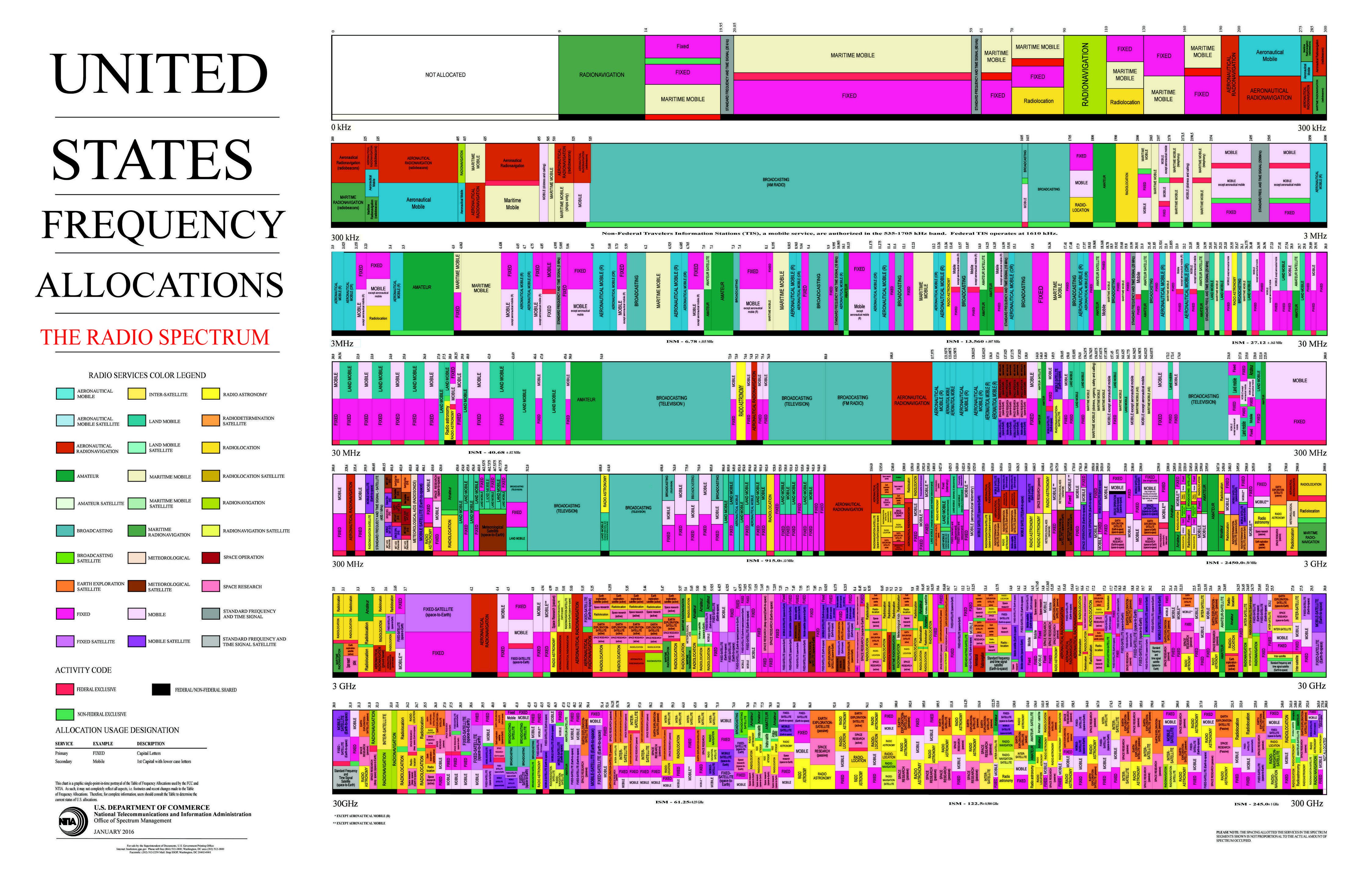
Although 300GHz may sound like a lot of spectrum, not all of it is suitable for communication, and, as the chart suggests, there are many users. For IoT, the so-called ISM bands are of particular interest, as they enable local communication with small antennas and power. Unlike other spectrum, no license is required to use the ISM bands.
Of all ISM bands, the 2.4 to 2.5GHz band gets presently most use for IoT applications and is used by standards including WiFi and Bluetooth. This is only 100MHz bandwidth for all users in the same space (e.g. building). Although RF transceivers use a wide range of clever solutions to enable coexistence, interference cannot be avoided in all cases with effects ranging from reduced data rate to transmission errors to outright failure to connect. The situation is not helped by microwave ovens using the same frequencies!
3.2. Modulation
Modulation is the process of packaging electronic signals for RF communication in a chosen frequency band. Although modulation of analog signals such as audio is possible, all modern wireless communication systems transmit digital data.
Figure 3 shows a digital signal, one bit at a time, and the corresponding modulated waveform. Each logical 1 is represented by a short burst at the carrier frequency (e.g. 2.45GHz for transmission in the 2.4 … 2.5GHz ISM band). The absence of a signal codifies a 0.
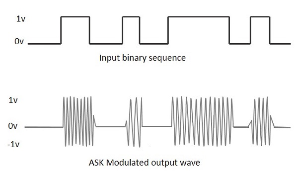
This form of modulation is called amplitude shift keying (ASK). Although simple, it has a number of drawbacks. In particular it is very susceptible to noise and fading which predominantly affect signal amplitude and are both common in RF communication.
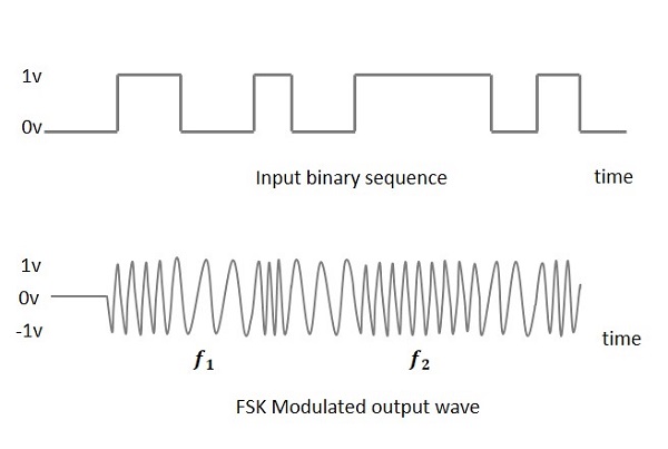
Alternatives such as frequency shift keying (FSK) are less susceptible to noise and therefore achieve lower bit error rates. Figure 4 shows frequency modulated signal which alternates between two carrier frequencies to encode a binary signal. Since variations in amplitude to not affect frequency, this signal is less prone to corruption in the presence of interference. This comes at the expense of being less “spectrally efficient” than ASK. More sophisticated modulation schemes such as phase shift keying (PSK) retain the better noise immunity but do not suffer from this drawback.
3.3. RF Signal Propagation
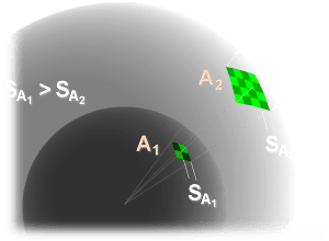
As electromagnetic waves travel, the power density decreases with the square of the distance due to spreading, as illustrated in Figure 5. The ability of the receiver to decode small signals therefore sets a limit on the maximum communication distance and rate. Increasing transmitter power can extend this limit but in practice is constrained by regulatory limits and power dissipation.
In free space, electromagnetic waves spread at the speed of light \(c=299,792,458 \text{m/s}\). The wavelength is inversely proportional to frequency:
For \(f=1 \text{GHz}\), \(\lambda=30 \text{cm}\). The free-space pass loss is
where \(d\) is the distance between the transmitter and receiver. For example, doubling \(d\) decreases the received signal power by a factor four. In matter (rather than free space), the attenuation is greater than predicted by the equation.
The attenuation being inversely proportional to wavelength, or, equivalently, proportional to frequency favors low frequencies for great distance or low transmitter power. This however comes at the expense of reduced data rate. In battery powered applications this may be an acceptable tradeoff.
3.4. Multi-Path Fading
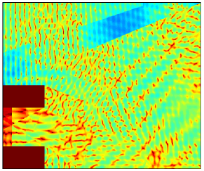
Especially indoors, other phenomena limit the range and quality of communication. Figure 6 shows a color coded map of received RF power in an office setting. Perhaps surprisingly, the received signal strength and therefore quality of communication varies greatly over small distances: while good reception is possible in one spot, the situation is much worse only a few centimeters away, only to improve again a short distance farther.
The reason for this is multi-path RF propagation. Much light light beams, RF waves, upon hitting an obstacle such as a wall or furniture, can penetrate it, be reflected, or a combination of the two.
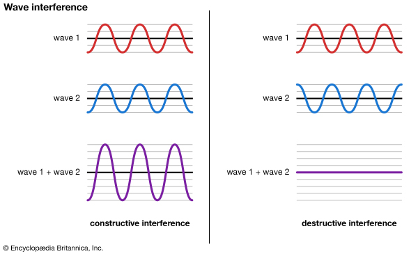
Figure 7 illustrates the situation. The electromagnetic wave reaches the receiver via more than one path, each with a different length. Each beam is therefore subject to a different delay, resulting in different phase shifts. At the receiver antenna the waves add. As Figure 8 illustrates, waves can add constructively or destructively (or anything in-between), depending on phase. At 2.5GHz, the wavelength of a electromagnetic radiation in free space is \(\lambda = c/2.4\text{GHz} = 12\text{cm}\).
This explains how small changes of position can result in large variations of received signal strength and, consequently, reliability and speed of communication. In the presence of moving objects, e.g. doors that open or close or people moving around, the changes are dynamic.
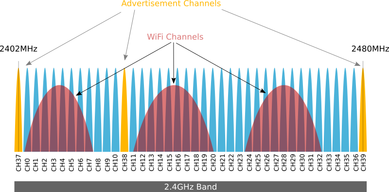
Successful wireless standards incorporate features to overcome or at least reduce this problem. For example, bluetooth divides the 2.4 … 2.5GHz band into 40 non-overlapping channels (Figure 9). Because each occupies a slightly different frequency, destructive interference occurs at different locations. Information is then transmitted over several channels and combined at the receiver. Packets that are lost are resent.
4. Wireless IoT Connectivity
4.1. Options
An ideal wireless solution would have unlimited speed and range, error-free, and consume no power. Of course, ideal does not exist in the real world, and consequently a large number of standards are used, each with with strength' and weaknesses. The list below is by no means exhaustive, and new solutions emerge regularly.
- WiFi
-
WiFi provides a direct path to the internet. It achieves fast communication rates over moderate distances at the expense of relatively high power dissipation (>500mW while transmitting).
- Bluetooth LE
-
BLE has applications e.g. in building automation, fitness devices where it is used to send small amounts of data over up to 30 meters, depending on the environment. Internet connectivity is achieved with a gateway (e.g. a smart phone) when needed. Relatively low power dissipation make it a good choice for battery operation.
- Cellular
-
The advantage of cellular communication is almost universal coverage in urban spaces. New standards (5G) promise to better address the needs of IoT: small and intermittent packets, security, flexible licensing and billing. IoT devices with on-board cellular modems are available from several vendors.
- Wireless Mesh
-
Applications such as home or industrial automation often rely on sensors that must operate for many years without maintenance. Often battery power is the only option, and hence calls for ultra-low power dissipation. This calls for infrequent communication and small packets combined with low power radio circuits. Unfortunately reducing power dissipation especially in the transmitter also reduces communication range, limiting coverage area. Mesh networks attempt to overcome this limitation by deploying a dense network of individual nodes. Each node can be reached by several neighbors who can forward packets to cover a large area. Standards that rely on mesh networking include Zigbee, Z-wave, and OpenThread. Many of these standards operate in sub-gigahertz ISM bands to leverage reduced attenuation of electromagnetic radiation. Reliability is a challenge in mesh networks.
4.2. WiFi
WiFi has become widely available both in corporate settings and homes. Access points are easy to set up and connect to the internet. Fast connection speeds and usually affordable or even free access make WiFi the wireless technology of choice for connecting to the internet where it is available.
These same advantages also translate to IoT applications, albeit with a few caveats. While direct connection to the internet is attractive for applications, it also poses challenging security concern. The combination of limited processing power and lack of support of established solutions for most IoT development platforms add to the challenge. Threats include compromised data that has not been properly encrypted before transmission, unauthorized access to hardware such as machinery connected to the IoT device, but also the possibility of viral infection that turn IoT devices into a threat to other internet users. All of these scenarios have and continue to occur in practice.
Because of this, it is often prudent use an intermediary with more processing power and security features as a proxy between IoT devices and the internet and rely on local communication through e.g. Bluetooth for communication between the IoT device and the proxy.
The second drawback of WiFi concerns primarily battery operated devices and stems from the relatively high power dissipation of WiFi radios. For example, many WiFi chipsets consume in excess of 200mA during transmission. Duty cycling, i.e. powering the radio only for brief periods to send data, helps, but is still limited by the long time taken to establish an internet connection of typically many seconds during which the radio dissipates power but transmits or receives no data. Other technologies such as Bluetooth LE which have been optimized for low power, can be a better choice in situations that demand battery operation for prolonged times, sometimes many month.
These concerns notwithstanding, WiFi is a good choice in many situations.
4.2.1. WiFi Connection
For MCUs with on-chip or attached WiFi transceiver, connecting to the internet is straightforward:
import network, time

wlan = network.WLAN(network.STA_IF)      (1)
wlan.active(True)
if wlan.isconnected(): return            (2)
print("Connecting to Wifi ... ")
wlan.connect('SSID', 'password', 5000)   (3)

for _ in range(30):                      (4)
    if wlan.isconnected():
        print("Connected to WiFi!")
        break
    time.sleep_ms(100)
if not wlan.isconnected():               (5)
    print("Unable to connect to WiFi")
wlan.disconnect() (6)| 1 | Configure as WiFi client. Some implementations also support configuration as WiFi access point. |
| 2 | Don’t wait if connection is already established. |
| 3 | Attempt connection. Supply the correct SSID and password of the WiFi access point you are connecting to. |
| 4 | Wait for connection to be established or give up on failure after 3 seconds. |
| 5 | Print error message if connection failed. |
| 6 | Free up resources if connection failed. |
Upon successful connection, the IoT device receives an internet address from the DHCP server (part of the access point/router it is connected to). Use the following statement to print out this address:
print("IP", wlan.ifconfig()[0])prints the IP address, e.g. 192.168.1.78. This value depends on the network and can be different each time the device connects.
Needing a wired connection to learn the IP address of a device is not always a practical solution. Alternatives are (1) using a relay with known public address (e.g. MQTT broker) or (2) mDNS, a feature that “broadcasts” a user-friendly name on the local network, also known as Bonjour.
Advertise microcontroller as my_esp32.local on the local WiFi subnet.
hostname = "my_esp32"
print("start mDNS server, hostname", hostname)
mdns = network.mDNS(wlan)
mdns.start(hostname, "MicroPython REPL")
mdns.addService('_repl', '_tcp', 23, hostname)
Once the microcontroller is connected, optionally set the on-board clock to the correct date and time with the code in Example 2.
Micropython maintains an internal clock that needs to be initialized to the correct date and time. This can be accomplished by fetching those from the internet using the code shown below:
rtc = machine.RTC()
rtc.ntp_sync(server="pool.ntp.org")
for _ in range(100):
    if rtc.synced(): break
    time.sleep_ms(100)
if rtc.synced():
    print(time.strftime("%c", time.localtime()))
else:
    print("Unable to get ntp time")
This uses the Network Time Protocol (NTP).
With WiFi activated, the microcontroller can be programmed over the web. To enable this feature, follow the instructions in Example 3.
Start the telnet (REPL) server on port 22.
user = "my-user-name"
pwd  = "my-top-secret-password"
network.telnet.start(user=user, password=pwd)| The user name and password are transmitted without encryption and therefore provide almost no security. Use this only behind a firewall! |
With the telnet server started, connect to the Micropython REPL from a host computer with
telnet <ip>where <ip is the internet address of the microcontroller. You will be asked the username and password specified above. Programs such as shell49 also support wireless connections. See the documentation for the connect command.
4.2.2. Communication Protocols
Micropython network support implements network sockets, a programming interface for communicating over the internet that is the basis for implementing higher level protocols such as http or MQTT.
4.2.3. Application Examples
The examples below show how to get the current weather (Example 4), send an SMS (Example 5) and serve a simple webpage (Example 6) from the microcontroller. Similar techniques are used to connect to a wide range of other resources.
In addition to human readable forms, many weather forecasts are also available in machine readable form. This example shows how to access the forecast from Wunderground.
First create an account at https://www.wunderground.com/weather/api and take note of the api key and http url example.
Then use the following template to access current weather conditions:
import urequests as requests                          (1)

res = requests.get(
"http://api.wunderground.com/api/1d7486ee37eb4276/conditions/q/CA/San_Francisco.json")
                                                      (2)

print(res.json()['current_observation'], end='\n\n')  (3)

weather = res.json()['current_observation']
print("Temperature", weather['temp_f'], "F")          (4)
print("Temperature", weather['temp_c'], "C")
print("Weather ", weather['weather'])| 1 | Import the python request library. Micropython calls it urequests to alert to the fact that only a subset of the full functionality is implemented. |
| 2 | URL and api key you got from wunderground |
| 3 | Print complete dict of current conditions, formatted as json for readability. |
| 4 | A few interesting values |
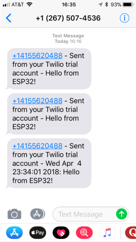
Even microcontrollers without a cellular modem can send text messages using services on available the internet.
This example shows how to use twilio for this purpose.
-
Twilio requires base64 encoding, which is not available by default in Micropython. Grab it from https://github.com/micropython/micropython-lib/blob/master/base64/base64.py and copy to the microcontroller.
-
Create an account at https://www.twilio.com.
-
Get a twilio phone number (from the
usagetab). -
Take note of
auth_sidandauth_tokenand copy to the code template below.
import urequests as requests
from base64 import b64encode     (1)
import time

# Credentials                    (2)
auth_sid    = "AC84e26324d90473624d90476324d9047"
auth_token  = "ba0ad421bd69da0b5f041a74d"
to_number   = "+15105523503"
from_number = "+14155770289"

# sample message                 (3)
msg = "{}: Hello from the MCU!".format(time.strftime('%c'))

data = "To={}&From={}&Body={}".format(to_number, from_number, msg)

def auth(user, pwd):             (4)
    """Twilio uses basic authentication"""
    return (b64encode(
                b':'.join((auth_sid.encode('latin1'),
                           auth_token.encode('latin1'))))
           ).decode('ascii')

response = requests.post(
    url="https://api.twilio.com/2010-04-01/Accounts/{}/Messages".format(auth_sid),
    data=data,
    headers={
        'Authorization': 'Basic {}'.format(auth(auth_sid, auth_token)),
        'Content-Type': 'application/x-www-form-urlencoded',
    },
)                                (5)

# print success/error messages
print()
print("response.text =", response.text)| 1 | Import the base64 library you downloaded. |
| 2 | Update this section with the values you obtained from twilio and the phone number you want to send an SMS to. |
| 3 | Compose a message. The sample simply sends the current time and Hello. Be creative. |
| 4 | This function is used to encode the auth_sid and auth_token in base64 format, as required by twilio. |
| 5 | Http post request instructing twilio to send the SMS on behalf of the microcontroller. |
Webservers for large internet sites use racks (or warehouses) full of powerful computers. But the minimum code for a server is actually quite simple and can run on a small microcontroller. This said, these platforms are in most cases not the best choices for this task.
The code below runs a webserver on the microcontroller that serves a single page with two buttons to turn an LED on or off.
Access from a browser with http://aaa.bbb.ccc.ddd, where aaa.bbb.ccc.ddd is the IP address of the microcontroller.
from machine import Pin
from board import LED
import socket
import time

html_response = """<!DOCTYPE html>
<html>
  <head><title>MCU LED ON/OFF</title></head>
  <body>
    <h2>MicroPython Web Server</h2>
    <form>                                               (1)
      LED:
      <button name="LED" value="ON"  type="submit">LED ON</button>
      <button name="LED" value="OFF" type="submit">LED OFF</button>
    </form>
    <br/>
    {}
  </body>
</html>
"""

led = Pin(LED, Pin.OUT)

s = socket.socket(socket.AF_INET, socket.SOCK_STREAM)    (2)
s.bind(('', 80))                                         (3)
s.listen(3)                                              (4)

while True:
    print("Waiting for connection ...")                  (5)
    conn, addr = s.accept()                              (6)
    print("Got a connection from %s" % str(addr))
    request = conn.recv(1024)                            (7)
    print("Content = %s" % str(request))
    request = str(request)
    if 'GET /?LED=ON' in request:                        (8)
        print('Turn led on')
        led(1)
    if 'GET /?LED=OFF' in request:
        print('Turn lef off')
        led(0)
    t = time.strftime("%c", time.localtime())
    conn.send(html_response.format(t))                   (9)
conn.close() (10)| 1 | HTML defining two buttons to turn LED on or off. |
| 2 | Create a socket for the webserver to accept connections on. |
| 3 | Configure the socket to listen on port 80, the standard internet port for http. |
| 4 | Maximum number of unaccepted connections before refusing new connections. Choose a small value to not overload the microcontroller. Google uses a more powerful computer to handle search requests and presumably a larger number for listen. |
| 5 | Debug messages. Remove those once everything is working. |
| 6 | Wait for web browser to connect. |
| 7 | Fetch data sent by browser in response to clicking the LED ON/OFF buttons. |
| 8 | Turn the LED on or off as requested by the user. Here we use very simple code to extract this data from the request. Real webservers use more sophisticated parsers. |
| 9 | Send the html response with updated current date and time. |
| 10 | Close the connection (also a socket) to recycle resources and loop back to wait for a new request. |
Adafruit IO is an MQTT broker that saves and plots data received and also interfaces to other services. Here we show how to use it to send and SMS via IFTTT.
-
Create an account on Adafruit IO and IFTTT
-
Create a feed on Adafruit IO, e.g.
sms-feed -
On IFTTT, create a new applet (menu at top right). For
thisuseAdafruit(monitor feed based on Adafruit IO, selectsms-feed, and choose a condition, e.g. greater than 100), forthatuse SMS, click on the action and edit the message to your liking. -
Run the following code on the microcontroller:
from mqttclient import MQTTClient
from time import sleep

server = "io.adafruit.com"
# update with your values from AdafruitIO ...
aio_user = "ttmetro"
aio_key = "9116ce5879324984a604d9355ab83fe"

mqtt = MQTTClient(server=server, user=aio_user, password=aio_key, ssl=True)

# send SMS
mqtt.publish("ttmetro/feeds/sms-feed", "200")
Similarly, choosing Adafruit as the then action sends information from IFTTT back to AdafruitIO and the MQTT client on the microcontroller:
def mqtt_callback(topic, msg):
    print("mqtt got topic={}, msg={}".format(topic, msg))

mqtt.set_callback(mqtt_callback)
# create feed in AdafruitIO and set up Applet in IFTTT to send data ...
mqtt.subscribe("ttmetro/feeds/ifttt-info")

# listen for mqtt messages
for i in range(1000):
    mqtt.check_msg()
    sleep(1)
Many other things to try: blink LED based on button push on smart phone (install IFTTT app), get SMS or email on the MCU, turn on the coffee maker (or whatever appliance) from the MCU, react to voice commands given to Amazon Alexa, smartphone apps, etc.
4.3. Bluetooth Low Energy
Bluetooth was initially conceived for transmitting continuous data (e.g. music to head sets) and later extended with a low energy mode to support sensors and related applications that transmit small amounts of data infrequently. Since those applications are often battery powered, low energy consumption is of great importance. The original Bluetooth standard is still supported and sometimes referred to as Bluetooth classic.
Table 1 shows a comparison of different wireless communication standards. Bluetooth LE supports considerably lower data rates than the other two options. In most applications, only a small amount of data is sent infrequently and the radio powered down when idle. The short time required to establish a connection is the key to low average power dissipation. It greatly reduces overhead especially over solutions such as WiFi which can take several seconds from powering up to actually sending data. Manufacturers report life times of up to two years of Bluetooth LE devices powered by a coin cell battery[1].
| Specification | BT LE | BT Classic | WiFi |
|---|---|---|---|
Throughput[2] |
~ 0.3Mbps |
~ 2.1Mbps |
> 10Mbps |
Current[3] |
<15 mA |
<30 mA |
>150 mA |
Time to connect[4] |
6ms |
100ms |
? |
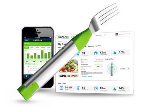
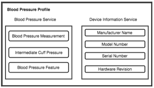
Unlike WiFi (or, more accurately, TCP/IP) which leaves it up to the applications to decide what information to transmit, Bluetooth LE uses the Generic Attribute Profile (GATT) or organize data by Service and Characteristic. As an example, Figure 11 shows a blood pressure meter with two services exposing measurement data and information about the device itself. Manufacturers can also create ad-hoc profiles in situations where the official ones are not a good fit or in an effort to prevent interoperability with devices from competitors.
Countless BLE devices are on the market from tags helping users find lost keys to toothbrushes with motion sensors giving feedback on the quality of brushing. Figure 12 shows a fork with integrated pressure sensor enticing users to eat slowly. Optimistic market forecasters expect over $50Bio sales in 2025.