This is the second of three labs on motors. In this installment we will use feedback to build the equivalent of “cruise control”, the ability of the motors to turn at a desired speed (RPM) regardless of load (within the torque limits of the motor).
| Refer to the discussion in the lecture for background. |
1. Prelab
In the previous lab we “informally” checked what happens if the motor is loaded by slowing it with our fingers. The same thing of course would also happen if the robot was going uphill, or pushing something. If it went downhill, it would speed up.
This load dependent behavior is often undesirable. For example, in many applications a robotic arm or machine is required to move at a given speed regardless of load. One solution would be over-designing the motor, such that typical loads have negligible impact on its output. Obviously this would be very inefficient.
A better approach is to use feedback. Imagine how you keep a car (without electronic cruise control) going at constant speed: you watch the speedometer, and if the cruising speed is below a desired value push the throttle, and, conversely, let up if the vehicle is going faster than the desired speed.
We will realize the same behavior in our robot with computer control. For this we need three elements:
-
A means to detect the actual speed to compare it to the desired velocity. We will use the “encoders” for this purpose.
-
The capability to control motor speed or torque. The H-bridge, also introduced in the last lab, serves this function.
-
A controller, to be designed and tested in this lab.
1.1. Proportional Control
Proportional control is the simplest form of automatic control. We are already familiar with this type of control from our use of operational amplifiers[1]
In the space provided below, draw a block diagram of proportional speed control, showing the motor, encoder, H-bridge, and controller.
Write the code for proportional control of a single motor, using the template shown below:
class MotorController:

    def __init__(self, motor, encoder):
        '''Controller for a single motor
        motor: motor driver (DRV8833)
        encoder: motor encoder (Encoder)
        '''
        self.mot = motor
        self.end = encoder

    def p_control(self, desired_cps, P=1):
        '''Set motor control to rotate at desired_cps'''
        actual_cps = ...
        error = desired_cps - actual_cps
        self.mot.set_speed(P*error)
        # return speed (e.g. for plotting)
        return actual_cps
Save your program as motor_controller.py.
To use this class, first call the constructor with DRV8833 and Encoder instances from the prior lab. Then call p_control periodically (e.g. every Ts=20ms) using a timer:
import ...

desired_cps = ...    # controller setpoint
P = 1                # controller proportional gain
Ts = 20              # controller operating period in [ms]

controller = MotorController(...)

def callback(timer):
    global controller, desired_cps, P
    # proportional control and print actual_cps (for plotting)
    print(controller.p_control(desired_cps, P))

timer = Timer(0)
timer.init(period=Ts, mode=..., callback=...)
Save your program as p_controller.py and upload to the MCU and gradescope.
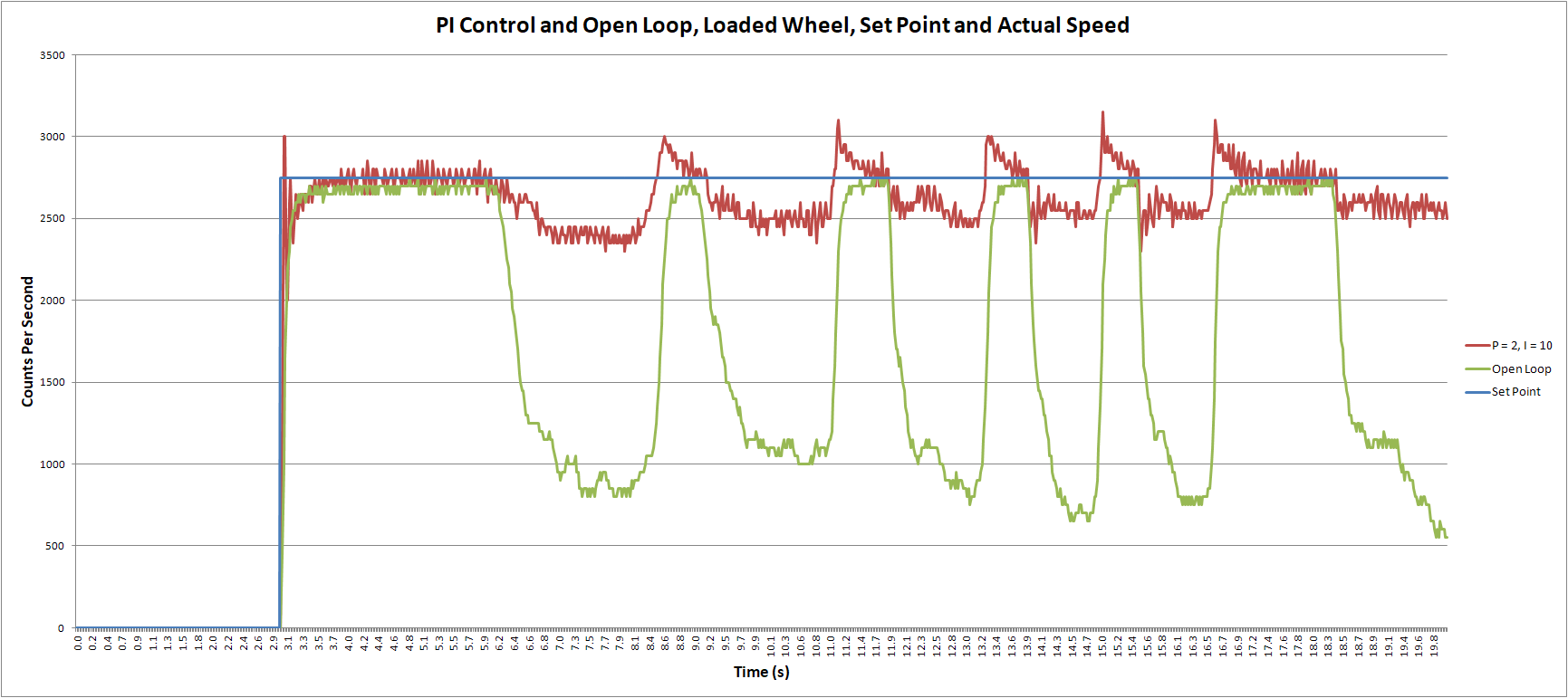
Figure 1 shows a typical result (when you do this experiment in the lab the output will differ slightly because of variations of the breaking force and system parameters). The plot has three traces: the desired rotation rate (Set Point), actual rate without cruise control (Open Loop) and in red the result with proportional control for P=2.
| Controller parameters may differ in your setup. Experiment with the values! |
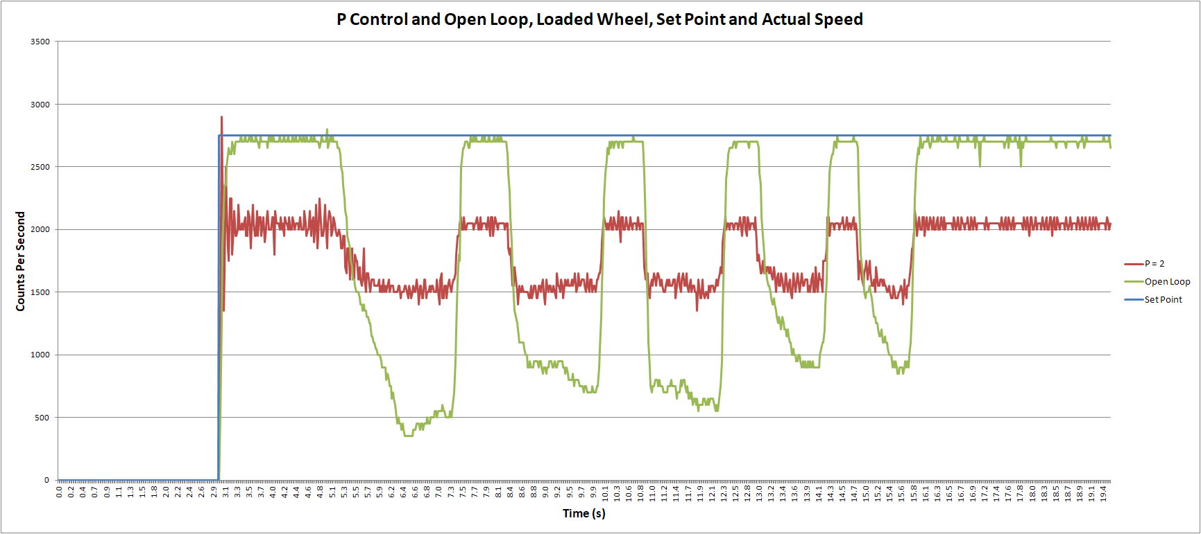
The controller significantly reduces the variation of the rotation rate under load. However, it also introduces a large systematic error: the actual cps, even without load, is considerably less than the controller input (desired_cps).
We have not observed this systematic error when using feedback with operational amplifiers. What’s different? In our applications of feedback we always assumed that the gain is infinite. This is often a valid assumption - the openloop gain of many operational amplifiers, for example, is in excess of 105 - but it is not correct for our motor.
What about increasing the controller gain P to reduce this error? Figure 2 shows the result. Higher P indeed results in reduced systematic error, but also produces significant oscillations just after the step has been applied.
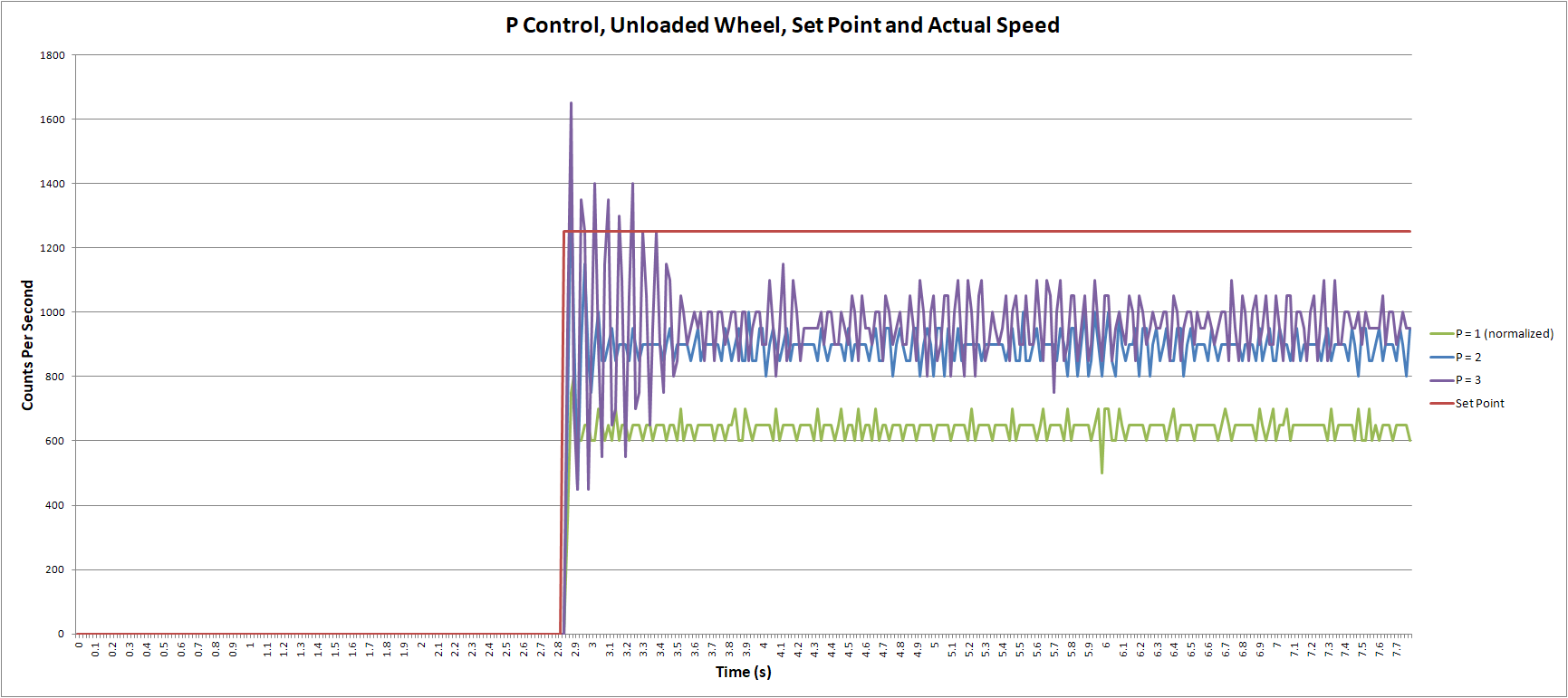
Moreover, the systematic error is still significant. Try even higher values of P in the lab to see if you can make the systematic error <5% of the step height (1250cps in the plot).
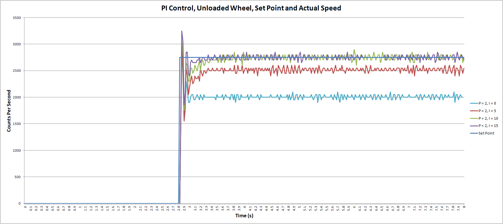
1.2. Proportional-Integral Control
Reducing the systematic error to zero requires infinite gain, but, as we have seen, this results in undesired oscillations. A compromise is a controller with infinite gain at DC (frequency = 0), but lower gain at higher frequencies. The simplest circuit with this characteristic is an integrator:
In this equation, x and y are the integrator input and output and \(\tau_i\) is the time constant.
In Python we approximate the integration with summation:
where \(x(kT_s)\) and \(y(kT_s)\) are the input and output of the integrator at the current time step \(kT_s\), \(I\times T_s\) is the integrator gain, and \(y(kT_s+T_s)\) is the new integrator output at time \(kT_s+T_s\).
Modify motor_controller.py as follows to add integral control:
class MotorController:

    def __init__(self, motor, encoder):
        # code from above
        ...
        # new: initialize integrator state
        self.integ = 0

    # add new method:
    def pi_control(self, desired_cps, Ts, P=1, I=1):
        actual_cps = ...
        error = ...
        # Ts in [ms]
        self.integ += error * Ts / 1000
        # clamp integrator, e.g. if desired_cps exceeds maximum motor speed
        self.integ = max(-150, min(self.integ, 150))
        self.mot.set_speed(P*error + I*self.integ)
        return actual_cps
Save your program as motor_controller.py and upload to the MCU and gradescope.
Also write pi_controller.py (similar to p_controller.py but calling pi_control rather than p_control) and upload to gradescope and the MCU.
2. Lab
Support the robot such that the wheels can turn freely. Test the cruise control, with first proportional control and then with the PI controller. To facilitate comparison, operate one motor with and the other without control (code from previous lab). Manually adjust the motor control duty cycle of the motor without control to match desired_cps.
Plot the step response for varying values of P. Your result should look similar to Figure 2. One you have found a good value for P, evaluate the behavior under load. Your output should look similar to Figure 1.
Checkoff:
Checkoff: