In three labs, we are going to build a robot that balances on two wheels like a Segway. In this first part we’ll assemble the robot and check out the motors.
1. Prelab
1.1. Motors
The robot uses two 75:1 Metal Gear Motors powered from 6 rechargeable NiMH batteries with 1.2V per cell or 7.2V total. Although the motors are rated for 6V, higher voltages can be used for brief periods of time for example to overcome obstacles, but do not exceed 6V for long periods of time.
| Use the AA battery pack for the motors only, not the Huzzah32! Use either a USB cable or LiPo battery to power the MCU. |
1.2. H-Bridge
We will use a DRV8833 H-bridge on a breakout board for controlling the motors. Download the datasheet (web search) and write code following the template below to control the direction and speed by modifying the PWM duty cycle (one DRV8833 controls two separate motors).
Template:
class DRV8833:

    def __init__(self, pinA, pinB, frequency=10000):
        '''Instantiate controller for one motor.
        pinA: pin connected to AIN1 or BIN1
        pinB: pin connected to AIN2 or BIN2
        frequency: pwm frequency
        '''
        # your code here ...
        pass

    def set_speed(self, value):
        '''value: -100 ... 100 sets speed (duty cycle) and direction'''
        # your code here ...
        pass

# Example:
motorA = DRV8833(19, 16)     (1)
motorB = DRV8833(17, 21)     (2)
motorA.set_speed(50)         (3)
motorB.set_speed(-70)        (4)
motorA.set_speed(0) (5)| 1 | Instantiate controller for motor A. Update pin numbers to match your wiring. |
| 2 | Ditto for 2nd motor. |
| 3 | Command motor to turn forward at 50% duty cycle (approximately half speed). |
| 4 | Run motorB in reverse. |
| 5 | Stop motorA. |
Implementation:
-
Use ``slow decay'' (Table 2 in the datasheet)
-
Note: PWM duty cycle 0% results in full speed, 100% stops the motor.
-
Hint: duty cycle 100% is the same as logic 1. You can use this to control motor direction, i.e. define two PWM channels, one for each motor control pin, and use duty cycle settings to control both speed and direction.
-
Frequency: Experiment in the lab with different values. At low frequency the motor stutters or vibrates, high frequencies produce an annoying audible noise. For small motors, 10kHz is often a reasonable compromise.
Save your code as drv8833.py, upload to the MCU, and submit to gradescope.
1.3. Rotary Encoders
Rotary quadrature encoders measure how quickly the motor is turning, providing both instantaneous “counts per second [CPS]” and “total count [count]”. The former, through appropriate scaling, is a measure of “revolutions per minute [RPM]” and the latter of “distance traveled”.
Fill in the template below to read the outputs from a single controller using the quadrature decoder unit in the ESP32.
class Encoder:

    def __init__(self, chA, chB, unit, counts_per_turn=12*75, wheel_diameter=70):
        '''Decode output from quadrature encoder connected to pins chA, chB.
        unit: DEC unit to use (0 ... 7).
        counts_per_turn: Number of counts per turn of the motor drive shaft. For scaling cps to rpm.
        wheel_diameter: In [mm]. For scaling count to distance traveled.
        '''
        # your code here
        pass

    def get_count(self):           (1)
        # your code here
        pass

    def get_distance(self):        (2)
        '''Distance traveled in [m].'''
        # your code here
        pass

    def get_cps(self):             (3)
        # your code here
        pass

    def get_rpm(self):             (4)
        # your code here
        pass

# Example:
import time

encA = Encoder(34, 39, 0)          (5)
encB = Encoder(36,  4, 1)          (6)

while True:
    print("Motor A rpm:", encA.get_rpm())
print("Motor B distance:", encB.get_distance(), "m")| 1 | Return total count from encoder. |
| 2 | Total count to distance traveled. Note: depends on wheel diameter. |
| 3 | Counts since last call to this function, divided by elapsed time. |
| 4 | CPS scaled to RPM. |
| 5 | Instantiate encoder readout for motor A. Update pin numbers to match your wiring. |
| 6 | Instantiate encoder readout for motor B. |
Write the code to read the magnetic encoders and return the result in CPS. Calculate the corresponding RPM and distance D traveled per encoder count C in meters (Hint: you need the motor specs and wheel diameter) and record your results in the table below.
|
|
|
Save your code as encoder.py, upload to the MCU, and submit to gradescope.
1.4. Circuit Diagram
Draw a circuit diagram showing the following parts:
-
Huzzah32
-
LiPo battery (used to power the Huzzah32)
-
7.2V battery pack (Remember: no connection to the Huzzah32!)
-
DRV8833 breakout board. Connect the 7.2V motor supply to
VIN. LeaveVMM,nSLEEP,nFAULT,AISEN,BISENunconnected. Connect the other pins per information from the datasheet and the breakout board description. -
DC motors and encoders. Tie
VCCto the 3.3V output of the Huzzah32,AandBto the ESP32, andM1andM2to the H-bridge. ConnectGND.
2. Lab
2.1. Assembly
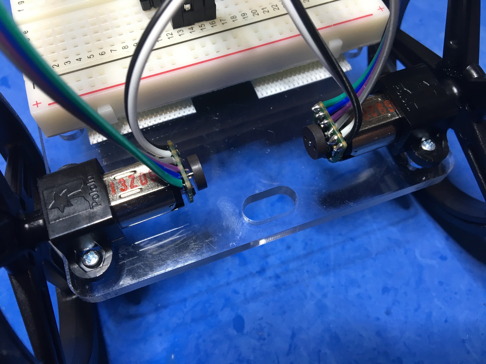
Start with soldering the magnetic quadrature encoders to the motors. Figure 2 shows the encoder with a ribbon cable soldered to it.
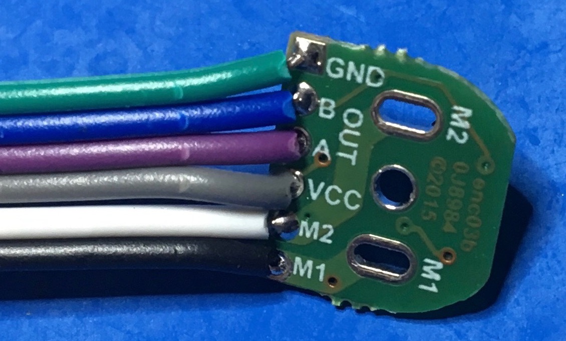
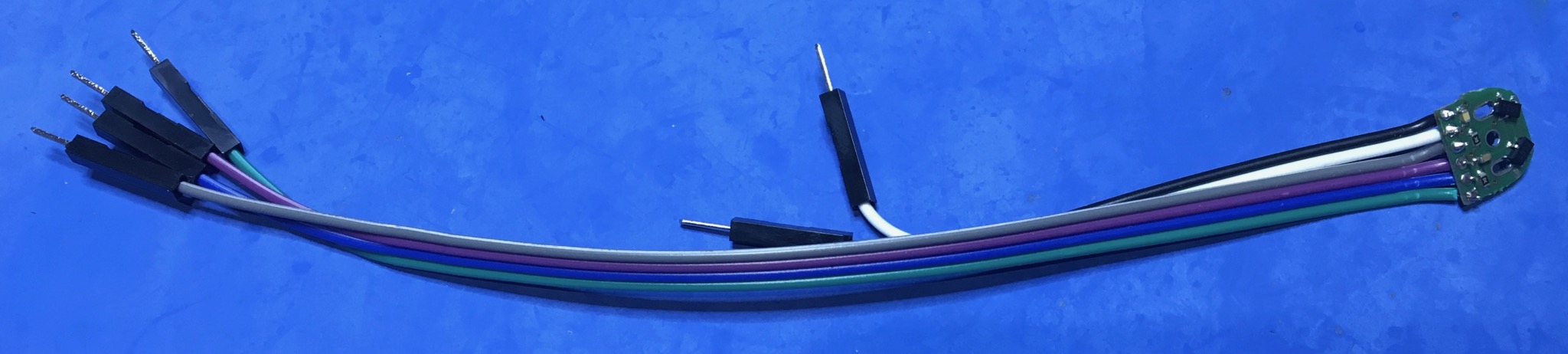
Cut a ribbon cable to the correct length (see Figure 3 and Figure 1 for a possible arrangement) and strip 2-3mm of the insulation. Tin each wire strand, insert into the encoder board and solder. Note the orientation of the cable on the label (opposite component) side of the encoder board. Position the encoder with inserted wires on the motor before soldering and make sure everything fits (the space for the wires between the motor and the board is very tight).
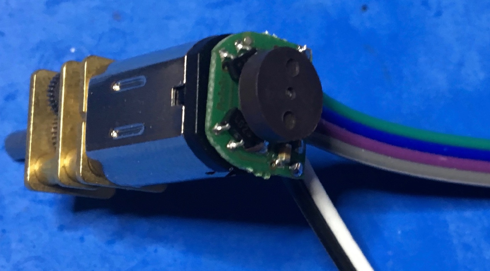
Next solder the encoder board with attached cable to the motor. Note that the components face away from the motor. Strip wires protruding more than about 0.5mm beyond the component side of the encoder board. Press fit the round magnet to the motor shaft (Figure 4).
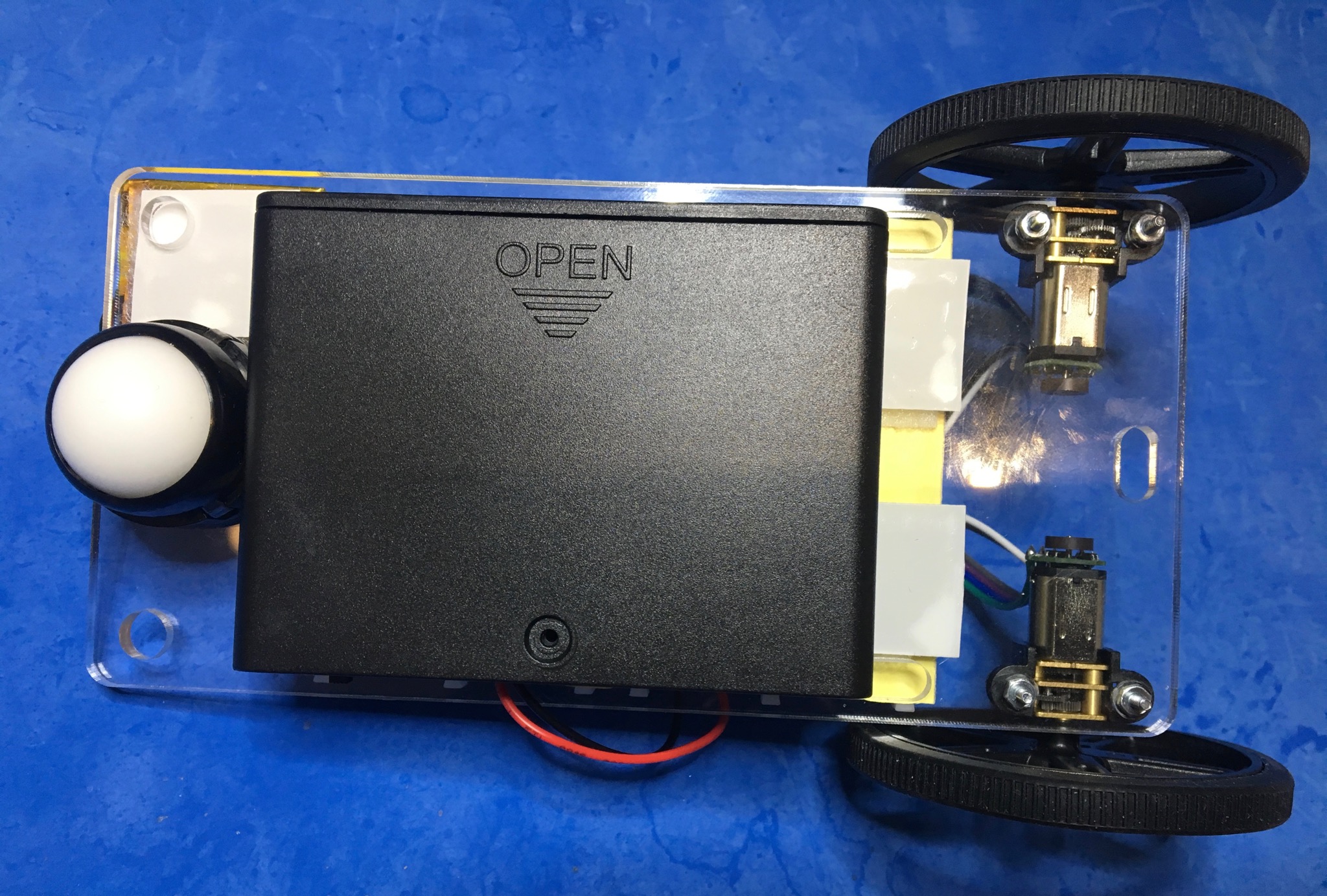
Proceed with attaching the motors and castor to the chassis mounting plate. Attach solder-less protoboards to the top and a battery holder (for six AA batteries) to the underside of the chassis using Velcro or double sided tape. Press fit the wheels onto the motor shafts.
| Install the batteries only after everything is assembled correctly and make sure you do not short the output! |

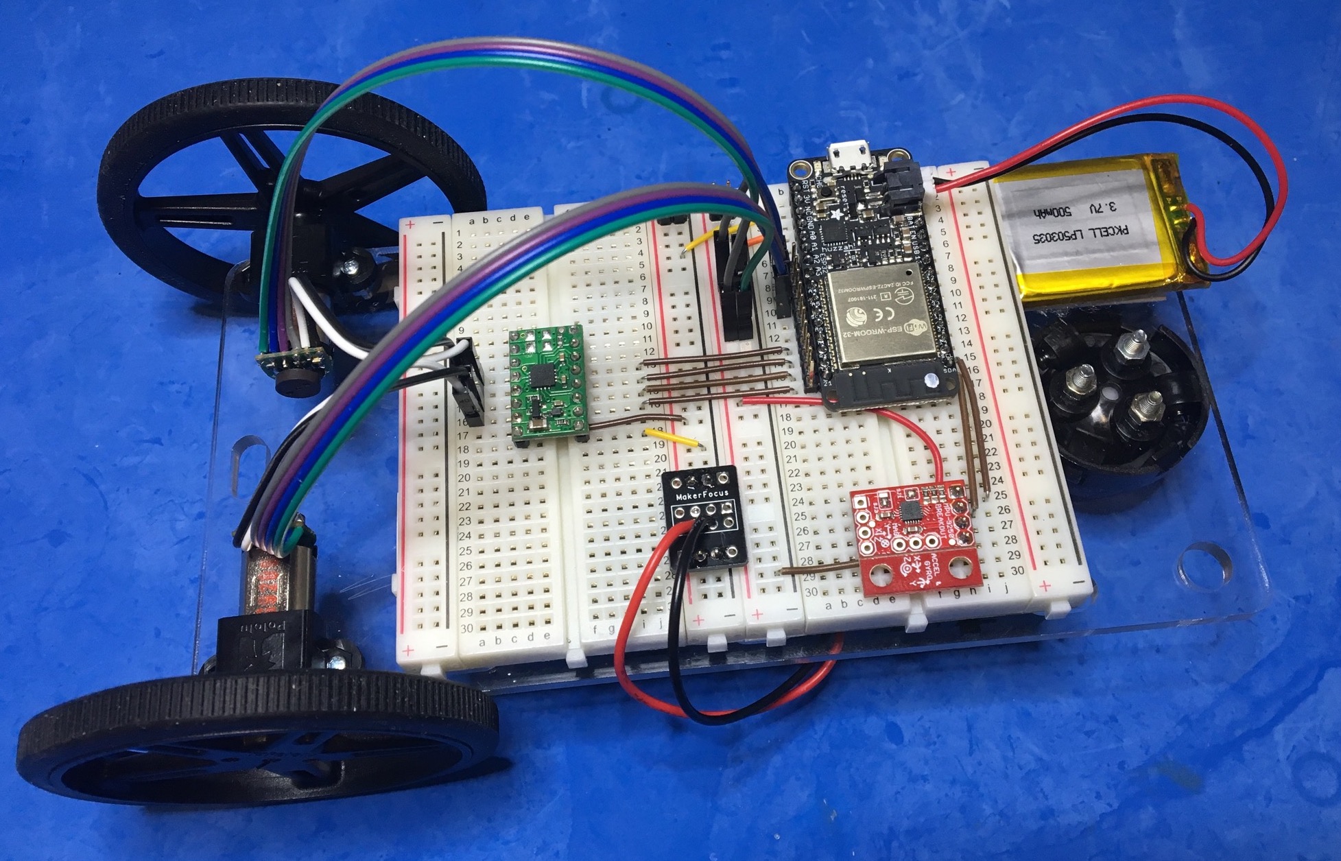
Now assemble the robot on the acrylic chassis plate shown in Figure 5. Add the motors, wheels, castor. Use velcro to attach the AA battery holder, breadboards, and LiPo battery using Figure 6 as reference. Then wire the circuit designed in the prelab.
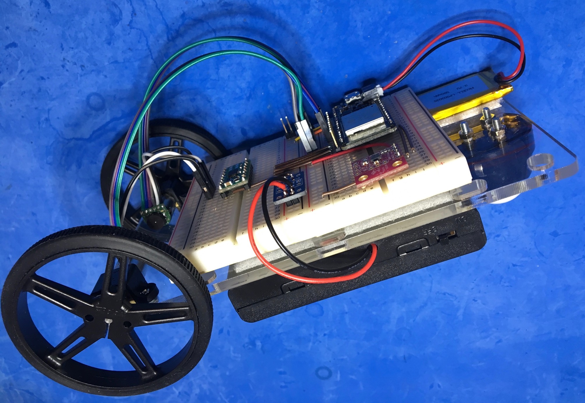
|
|
|
2.2. Motor testing
Now we characterize the motors. The motors are nominally identical, so you can run the complete tests with one motor only. But verify that both motors and encoders work properly.
Characterize unloaded motor speed in CPS under three conditions:
-
Voltage control. Use the lab supply and record CPS for Vmotor = -6 … +6V in 1V steps. Also record the minimum voltage at which the motor turns. Record your results in a graph showing measured CPS versus voltage.
-
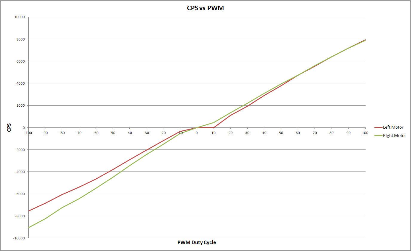
PWM control. Plot CPS for -100% … +100% duty cycle in 10% steps. Also record the minimum duty cycle at which the motor turns. Power the motor from the AA battery pack (make sure that it’s charged and the voltage is at least 7.2V without load). Record your results in a graph similar to that in Figure 7[1].
-
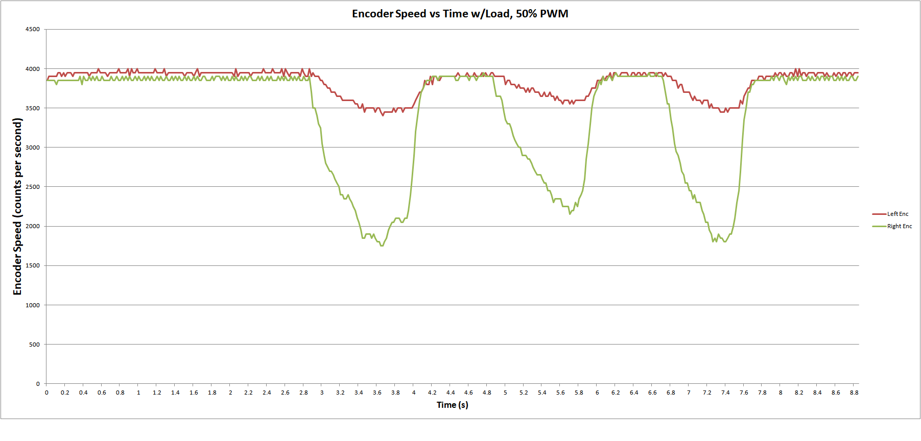
CPS under load: Full motor characterization includes testing under load. Lacking the proper lab equipment (Dynamometer) to apply a known torque load to the motor, we instead perform an “informal” test by loading the motor by lightly touching the wheel (do not stall the motor) and record CPS versus time. Your plot should look similar to Figure 8. In the next lab we will implement cruise control to maintain speed regardless of load.
Summarize your test results in graphs and the table below.
| Control | Minimum CPS[2] | Max CPS (abs) |
|---|---|---|
Voltage |
||
PWM |
Checkoff: