1. Overview
This group of three labs leverage the general purpose input-output (GPIO) features of the the microcontroller to interface a broad range of devices including a weight scale, audio synthesizer, and a capacitive touch sensor.
Some of the sessions may take more time. Many experiments do not need lab equipment and can therefore be completed outside the lab. You may also finish work in a subsequent lab, but organize yourself to complete all checkoffs by the end of the third session.
2. Prelab
2.1. Overview
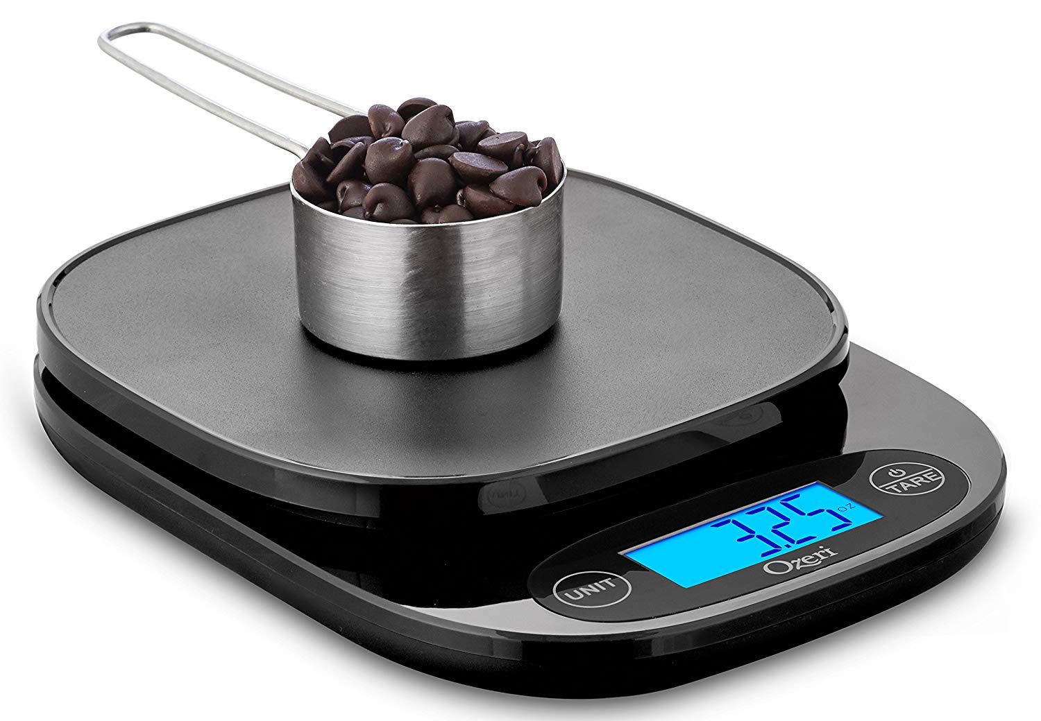
Kitchen scales have become pretty trivial, put the ingredients on top and the weight is displayed. But how do these devices work? Let’s build one to find out!
Target specifications:
-
Range: ± 1 kg
-
Zeroing button
-
Gram/ounces button
-
Battery powered
2.2. Load Cell
At the heart of the scale is a load cell (Figure 2), which measures force using four strain gages configured as a bridge as shown in Figure 3. The unknown mass is then determined from the measured force and gravitation constant.
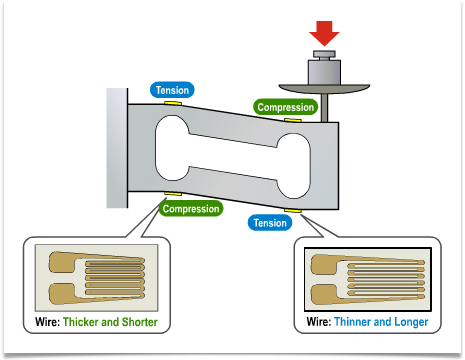

Calculate the resistance of ports A-B and A-C, respectively, as a function of resistance \(R_1=R_2=R_3=R_4=R\) of a load cell with no strain applied. You will need this result later to determine how to wire up the load cell.
Resistance A-B |
||
Resistance A-C |
Note it’s not \(R_3\)! |
Now calculate voltage \(\Delta V\) as a function of applied strain \(\epsilon\), gage factor GF, and voltage \(V_s\).
\(\Delta V\) =
2.3. Preamplifier and ADC
We will use the built-in A/D converter (ADC) of the MCU to convert the output voltage \(\Delta V\) to a digital representation. Unfortunately \(\Delta V\) is only a few milli-Volt even for a full-scale load of 1kg.
Calculate the digital output of the ADC for \(\Delta V = 3mV\). Assume that the ADC has 12-Bit resolution and \(V_{ref} = 3.3V \). Assume that for \(\Delta V = 0V\) the ADC output is zero.
ADC output:
Assuming that this value corresponds to 1kg, what would be the resolution of the scale, i.e. what is the smallest weight that can be detected?
Resolution: gram
We use an amplifier to gain up \(\Delta V\) before applying it to the ADC. Instrumentation amplifiers are perfect for this purpose. The INA126AP operates from supply voltages from as low as 2.7V up to 36V and can thus be powered from the 3.3V output of the Feather board.
Next we determine the required gain. The ADC accepts inputs from 0V to the supply, 3.3V[1]. However, the amplifier, supplied from V+ = 3.3V (and V- = 0V), can produce outputs only in a smaller range \(V_{\min}\) to \(V_{\max}\), illustrated in Figure 4. The situation is similar to a car engine which operates well at rpms from 700 to 4500 but poorly or not at all outside this range.
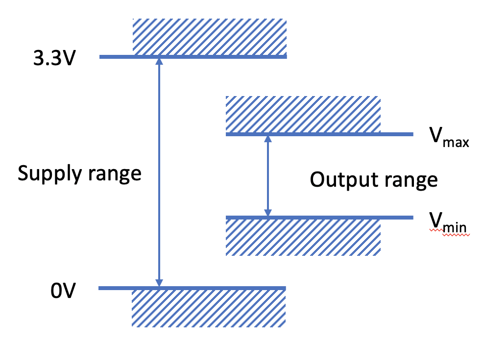
Determine the worst case values of \(V_{\min}\) and \(V_{\max}\) of the INA126 from the datasheet[2] and record them in the table below.
\(V_{\min}\) |
|
\(V_{\max}\) |
Now let’s modify our analysis for the actual available input voltage range of the ADC in the ESP32 (which is a bit unusual). The GPIO handout shows the input voltage range of the ADC for different settings. The widest range (called 11dB in the ESP32 datasheet) is very nonlinear and therefore unsuitable. Let’s use the 6dB-range instead, which accepts inputs from about 100mV to 1.8V.
| “Loboris MicroPython” returns the ADC output scaled to milli-Volts, rather than an integer code. See the manual for details. Further beware that the ADC in the ESP32 is not very accurate. |
We want to use the largest possible voltage range that meets both the ADC and amplifier output voltage limitations. For example, if an amplifier is capable of outputs up to 2V but the maximum input the ADC is only 1.5V, we would design the circuit to produce voltages that stay below the more stringent constraint, 1.5V in this case.
Note the minimum and maximum voltages that meet both amplifier and ADC limitations:
Min |
|
Max |
We will further constrain these values by a “safety margin” of about 200mV and map them to weights of 0 and 1kg. Record the final target voltages in the table below:
| Weight | Amplifier Output Voltage |
|---|---|
0kg |
\(V_{0kg}\) = |
1kg |
\(V_{1kg}\) = |
For 0kg, the amplifier input is \(\Delta V = 0V\) (ideally), and the output should be \(V_{0kg}\). This is accomplished by producing this voltage with a divider and connecting it to the amplifier reference terminal (tied to ground in the schematic in the datasheet and labeled “Ref” in the pin diagram). Note that this voltage is likely lower than halfway between the supplies. Generate it with a resistive divider or potentiometer.
Now we are ready to calculate the proper amplifier gain. Assuming \(\Delta V = 3mV\) for 1kg, what is the required amplifier gain \(G\) to get \(V_{1kg}\) at the output?
\(G\) =
Determine the value of the corresponding gain setting resistor, \(R_G\).
\(R_G\) =
Draw the complete circuit diagram of the weight scale including the bridge resistors, amplifier, and ADC input. Use a “triangle” for the amplifier, but show the power and “Ref” connections, and mark the pin number next to each connection (you will find these numbers in the datasheet and need them to wire the circuit in the lab).
Write the code to configure ADC pin ADC0 (any other ADC pin would do as well; refer to GPIO) and print its output once a second. Do not worry much about the exact values of gain and offset; you will adjust those in the lab to match the characteristics of the precise values of your components (which vary from part to part).
Write the code to read a button state connected to pin A21 (any other GPIO input pin would do as well) with “debouncing”:
3. Lab
3.1. Assembly
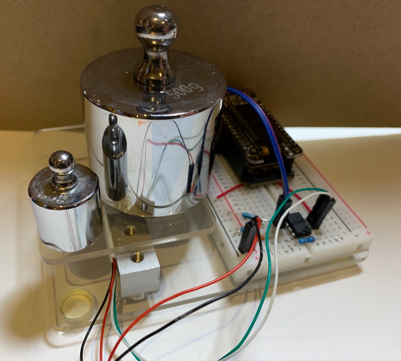
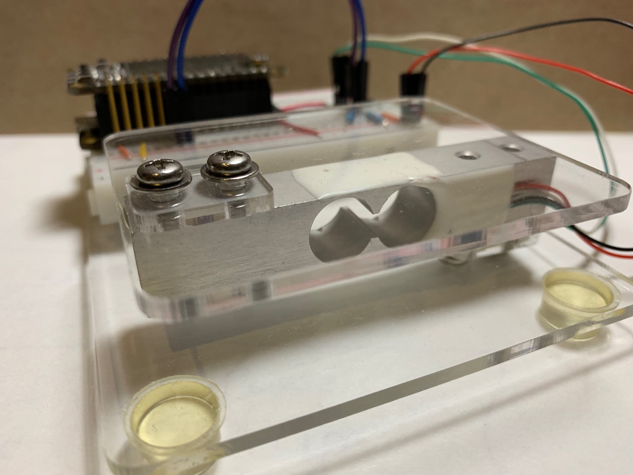
Assemble the weight scale. Figure 5 shows the complete setup. Attach the load cell to the base acrylic base (Figure 7[3]) using one of the spacers and the tray to the other end with the other spacer. Then attach rubber bumpers to the corners of the base. Keep the robot chassis for later.
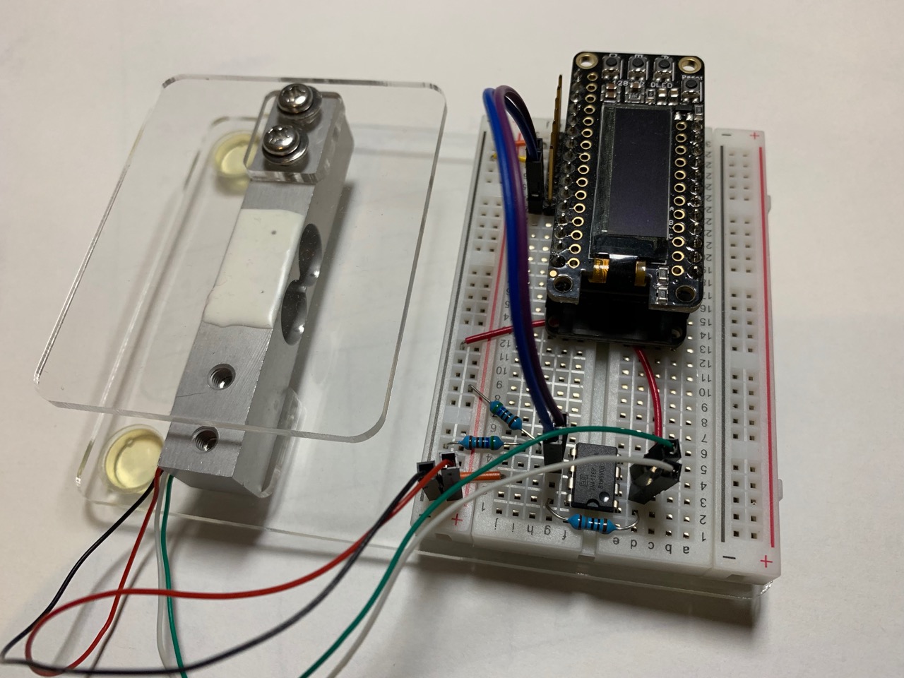
Solder a wire to each lead of the load cell so that it can be inserted reliably into a solderless protoboard. Using an ohm-meter, determine how to connect the load cell to the supply and amplifier and wire the circuit. Calculate appropriate resistor values to set the gain and design a voltage divider (use resistors in the range 1k … 25kΩ) to generate the reference for the amplifier.

Verify your wiring, e.g. by measuring the voltage applied to the bridge, amplifier reference. Once you are confident everything is correct, take the following measurements with and without posing a weight on the scale (use a reasonable weight, e.g. 500g or 200g).
| Parameter | No weight | With weight |
|---|---|---|
\(\Delta V\) |
||
Amplifier output \(V_o\) |
||
ADC output |
Likely \(\Delta V\) deviates from the ideal value of 0V with no weight on the scale. This is due to offsets in the circuit and can be corrected (if the error is small and does not overload the amplifier or ADC) in software.
Ask the instructor to checkoff your circuit and measurement results:
3.2. Tare and Units
Modify your code to zero the scale output each time the “tare” button is pressed (or whatever you like to call the button connected to the MCU).
With no weight on the scale, press tare to set the output to zero. Then place an appropriate weight (e.g. 500g or 200g) on the scale and record the output. Modify your code to display the weight in grams.
Use a second button to switch the output between grams and ounces. For illustration, try this function first without “debouncing” code, and then with “debouncing”. Briefly summarize your observations in the two cases below:
| Some (good) switches bounce only very briefly. In those cases you may not observe any effect of bouncing or see it only in a very fast program (that only reads the button and does nothing else). Counting button presses in a variable is a good way to diagnose bouncing. Suggestion: even if a particular switch exhibits no bouncing, it is a good idea to protect against incorrect behavior in case characteristics change or the button is replaced with a different specimen that happens to bounce. |
Congratulations! You built your own kitchen scale. Time to compete with the Chinese. Before, proudly show off your creation to the instructor for checkoff.
3.3. Autonomous Operation (optional)
A kitchen scale that must be connected to a lab computer or laptop to function is kind of kludgy. Easily fixed … just power it from the LiPo battery.
But where is the display? Just upload measurements to the cloud or attach a display!