Some of the basic components that you will need are in two introductory SLF files.
First play with the file gear.slf in SLIDE. Examine the influence of the various parameters. Study how the contact point between the wheels moves as the wheels turn. For wheels with different numbers of teeth, find out how large the teeth have to be made so that the wheels always stay in contact (in both directions) as the wheels turn. Find out at what tooth size interference occurs.
Now, using the useful pieces of this file, you should build your own true gearwheel generator. This is an introduction into the more powerful -- and more tedious -- aspects of programming in tcl. Construct your generator along the logical steps that one would use to design a practical gear.
Start with the gear ratio; the number of teeth that your generator can produce should vary from 8 to 40. Don't worry about the module m, since this is just a scale factor on the whole gear pair. Make sure you can easily select one of the two standard pressure angles. Set the addendum and dedendum to their usual default values.
Since I got the sense that many in the class have trouble with understanding and controlling the involute, I have created gear2.slf In which I have already calculated the adjustment of the top of the cogs to the addendum circle. (You can still change it with the the "cog face sweep factor.") Now you can focus on combining the two opposite flanks into a single cog.
And another late-night edition ...
If you have struggled long enough with making a decent gear wheel face,
then gear3.slf
will show you one way of doing it.
In this code, I am starting at the center and make one complete cog,
including space in-between and fillets, and also the axle hole ...
Since the number of teeth may vary, you will have to add or delete geometry as some of the sliders are moved -- not just modify vertex coordiantes or transformation matrices. The demo file Instancing.slf shows you how to do this cleanly by using the tcl commands "slide create point", "slide delete face", etc. Thus you should combine the useful parts of these two demo files to make a generator that gives properly designed gearwheels by default, but with an adjustable number of teeth and pressure angle. Make sure that you get this working properly in 2D first. Now add the bottom face and the side faces to make a 3D extruded spur gear.
Design an interlocking pair that properly moves under slider control. To obtain a "personalized" design, choose a gear ratio is equal to the ratio of the number of letters in your first name and in your last name. Choose one of the standard two pitch angles. Make sure that there is no interference. Calculate the contact ratio for your gears and make sure it is larger than 1.2; if not, make the necessary fixes. Then make your wheel 3D -- a simple sweep along a straight line segment will do the trick !
This is Phase One of your assignment.
Do this part of the assignment individually -- by 3/1/00.
In Phase Two, you will modify your generator so that it can produce bevel gears
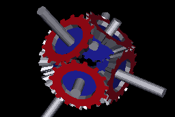
to be used in small assemblies such as the
"Octa Gear".
First calculate the virtual spur gear that lies in the "plane of action" -- i.e.,
the plane tangential to both back cones, and define the geometry of teeth in that plane.
Then wrap this geometry around the back cone to get the proper tooth shape.
If that step is too tough for you, you may omit it and conically project one tooth
directly towards the joint axle-intersection point.
You then instantiate theat bevelled tooth around the whole perimeter of the bevel gear.
Finally construct a suitable supporting disk for the teeth with an axle hole in it.
The output should be suitable to produce STL descriptions of gears
that can be fabricated on an FDM machine; the gears should lie flat on the x-y-plane
and their teeth should point upwards.
This second phase will done in working pairs.
This is the proposed list of working pairs:
Your gears should have an adjustable, cylindrical, central hole, so that the wheel can fit over a standard (metal) axle (say 4mm diameter by default). With this utility in hand, design a symmetrical cluster of gears. Start from a truncated cube, octahedron, dodecahedron, or icosahedron. Adjust the depth of the vertex truncation, and thus the sice of the truncation face, so that an simple integer gear ratio results. The pitch circles of the wheels should be the inscribing circles on the faces of this polyhedron.
Create a SLIDE file named cluster.slf that shows such a cluster in operation when a single "angle" or "time" slider is moved. If you run out of time, don't worry about making a manufactuarble central body, just let the gears float in space (with computer graphics magic). However, make sure that you adjust the rotation phases of the individual gears so that they properly interlock. In terms of showing an animation, Jane Yen's gear movie, comprising the files jane_gear.slf and MOVIE.tcl may come in handy as sources of inspiration or tcl program code.
When you get around to designing a suitable Platonic or Archimedean polyhedron with holes to hold the axles for the wheels, these files may be useful: CS285/CODE/REGPOLY/{ octa.slf , cubocta.slf , or icosidodeca.slf -- and also: Tcube.slf , Tocta.slf , Tdodeca.slf , Ticosa.slf , Ttetra.slf }. Add sink holes for the axles at each face center using boolean operations.