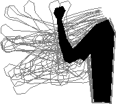
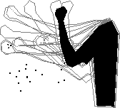
We trained an interpolation network using a single RBF to model the appearance of the arm as a function of endpoint location. Appearance was modeled as the vector of contour point locations, obtained from the synthetic arm rendering function. We first trained a single RBF network on a dense set of examples of this appearance function. Figure 2(a) shows results interpolating new arm images from these examples; results are accurate except where there are regions of appearance discontinuity due to workspace constraints, or when the network extrapolates erroneously.
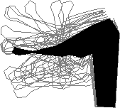
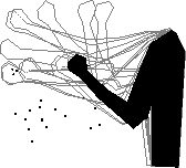
We applied our clustering method described above to this data, yielding the results shown in Figure 2(b). None of the problems with discontinuities or erroneous extrapolation can be seen in these results, since our method enforces the constraint that an interpolated result must be returned from on or within the convex hull of a valid example set.
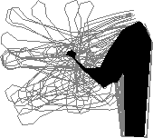
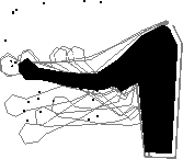
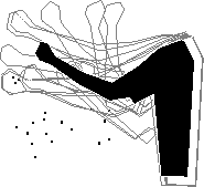
Next we applied our method to the images of real arms shown in Figure 3. Arm contours were obtained in a sequence of 33 such images using a semi-automated deformable contour tracker augmented with a local image distance metric [3]. Dense correspondences were interpolated from the values on the contour. Figure 4(a) shows interpolated arm shapes using a single RBF on all examples; dramatic errors can be seen near where multiple different appearances exist within a small region of parameter space.
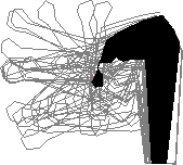
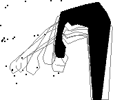
Figure 4(b) shows the results on the same points using sets of examples found using our clustering method; physically realistic arms are generated in each case. Figure 5 shows the final interpolated result rendered with both shape and texture.
    |
 (c) (c)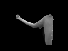             |