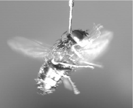
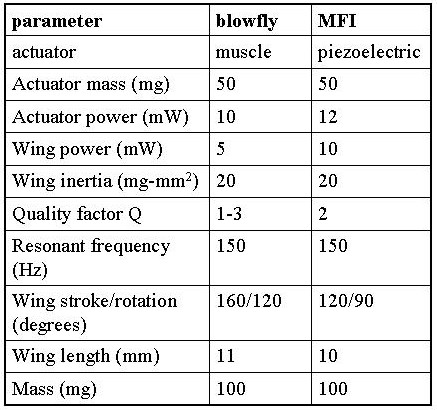
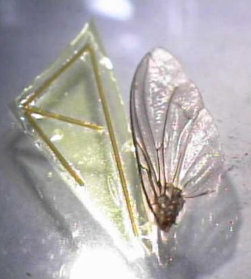
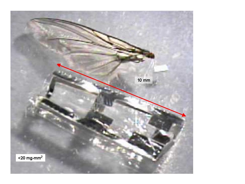
As a design target for the MFI, we are using the blowfly Calliphora (Figure 1), which is large enough for relatively easy assembly of actuators, thorax, wings, and electronics. A set of the most relevant parameters is shown in the table below. The first critical determination is whether enough mechanical power can be delivered to drive the wings. We found that the actuator mass for the MFI will be comparable to the blowfly as single-crystal piezoelectric actuators potentially have greater power density than muscle at high wing beat frequencies. The MFI needs to have comparable wing inertia and damping to keep Q low and controllability high.
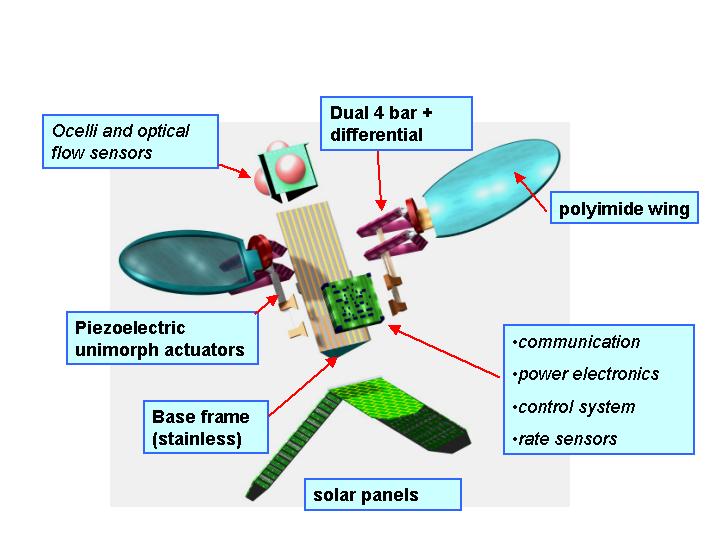
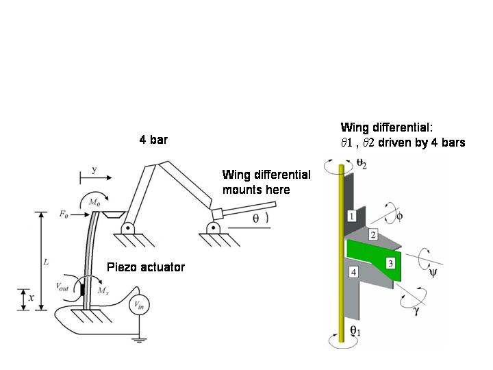
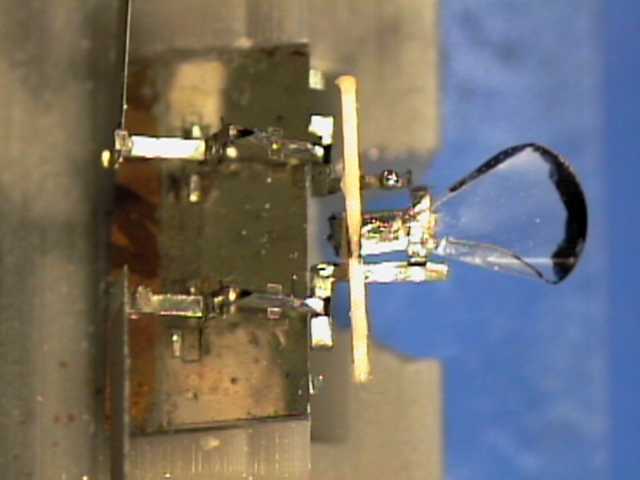
Our second key design consideration is a thorax structure which can transform small piezo actuator deflections into the large wing stroke and rotation required to achieve efficient flight. As shown in the artist's conception above, we will be using flexural 4 bar elements to provide sufficient wing stroke, combined with a miniature differential element to provide wing rotation. A low-inertia rigid wing is fabricated from polyimide (Figure 3).
|
|
|
|---|---|
| Figure 1. Calliphora | Table 1. Blowfly and MFI Parameters |
|
|
|
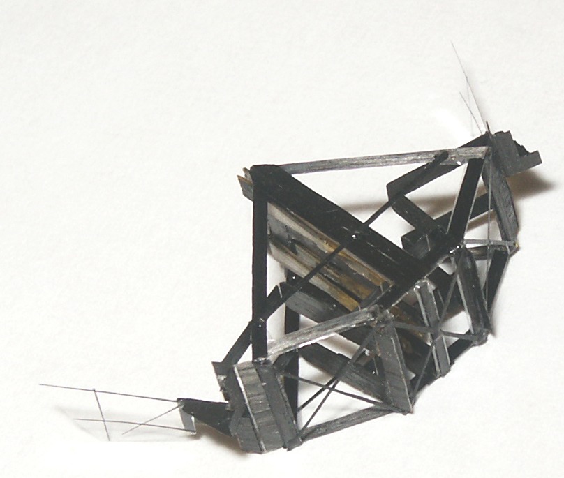
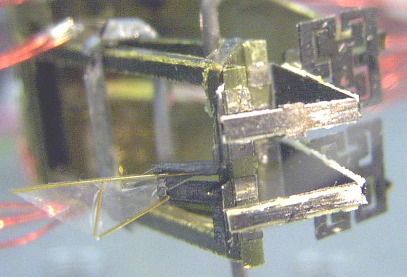
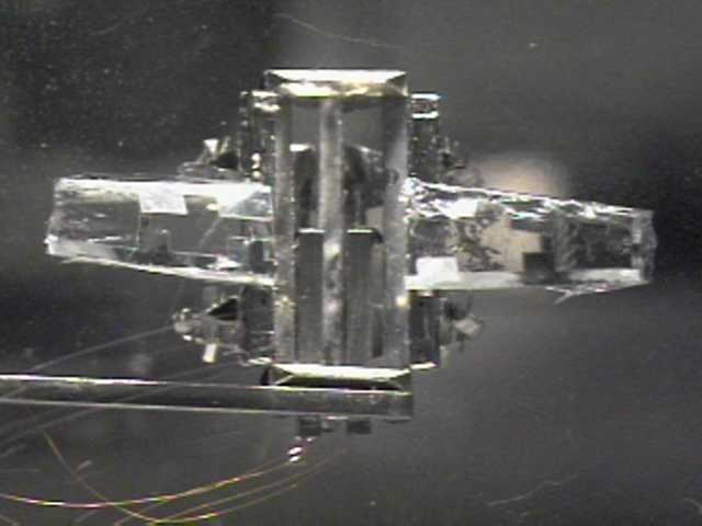
| Figure 2. Main MFI components. | Figure 3. MFI and Calliphora wing. |
The main MFI components and subsystems are shown in Figure 2. As of August 2001, we have fabricated the air frame, solar panels, actuators, wings, force sensors, and thorax mechanisms. Initial tests have shown generation of thrust forces from the MFI prototype on a flight mill. After we control lift and thrust on the flight mill, the next step will be to design a suitable power generation unit, flight control unit, and communication unit for remote control. Our initial plan is to concentrate on stable hovering, and to use simple optical sensing and a rudimentary on board gyroscope for insect attitude control and stabilty --- mimicking the control strategy used by flies. The eventual goal is to fabricate and demonstrate a stable and autonomous MFI.
last updated Dec. 29, 2001
Each MFI wing is driven through a compound kinematic mechanism which
converts the +- 1 degrees motion range of two piezoelectric bending actuators
to the +-45 degrees wing rotation and +-60 degrees wing flapping.
Each piezo actuator drives the input link of a 4 bar mechanism.
The two 4 bars drive the wing differential. When both 4 bars move in phase,
the wing has pure flapping. When there is a phase difference between the
two four bars, the wing rotates.
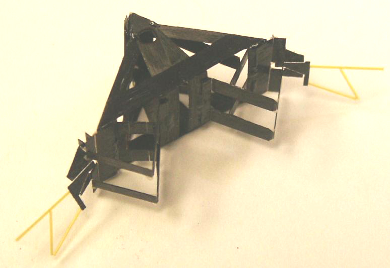
This page shows the evolution of the thorax design to its current
construction using carbon fiber links and polyester flexure joints.
Each wing drive uses 15 joints and provides 2 degrees of freedom.
Dec. 2003
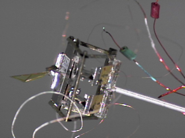
2 wing carbon fiber air frame and thorax with actuators.
Mar. 2003
Prototype 2 wing carbon fiber air frame and thorax with actuators.
Aug. 2002
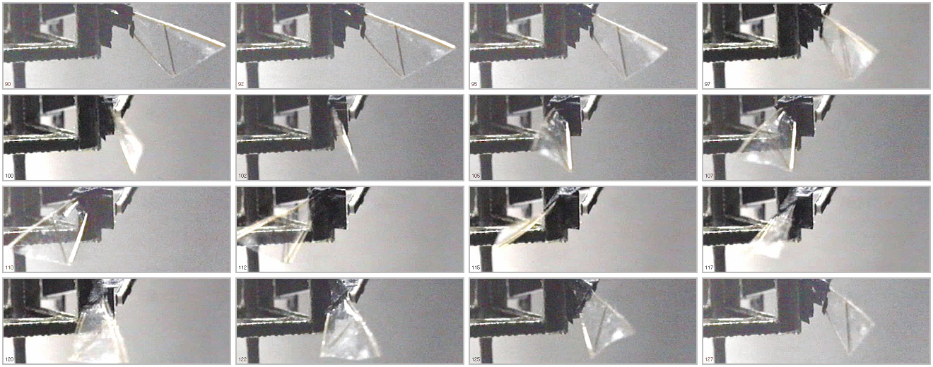
(left) 02lambda one wing flapper, 160 Hz resonant frequency.
(right) Wing stroke sequence at 160 Hz.
Aug. 2001
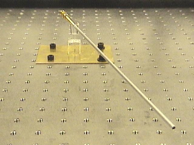
(left) Flight mill for constrained flight testing with 2 degrees of freedom.
(right) One wing flapper (with oversize frame) attached to flight mill.
Mar. 2001

(left) Wing constructed from 6 micron polyester frame with 2 micron face-sheet,
with Calliphora wing.
(right) Model of wing drive kinematics.
Structural integration test bed with 5x1 mm PZN-PT actuators,
and two 1 DOF wings.
(Missing wing differential).
Dec. 2000
(left) Two DOF thorax driven by pair of 16x3 PZT unimorphs, with 1 cm wing.
(right) Flapping and rotation at 40 Hz.
May. 2000
1.4X stainless steel thorax driven with PZT unimorph at low amplitude.
Mar. 2000
1.4X stainless steel thorax with polyester wings and flexural joints.
Sept. 1999
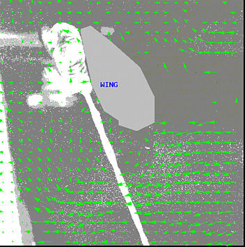
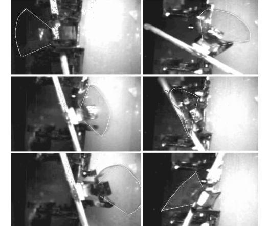
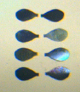
5X polyester fanfold wing structure beating at 17 Hz in wind tunnel. Complete stroke shown starting at bottom of stroke, upper left. Dark line is laser light sheet.
Aug. 1999
Large-scale fan-fold wing driven by voice coil actuators mounted in
wind tunnel for particle image velocimetry measurements.
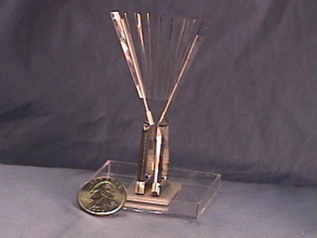
Stainless steel thorax structure with polyester wing.
Ken Chiang has started design of a conventionally actuated mockup of an insect to explore wing stroke kinematics and control. The wings will be approximately 10 mm in size and driven by push rods using voice-coil actuators. We have some preliminary flow images with low wing velocity. Flow Image
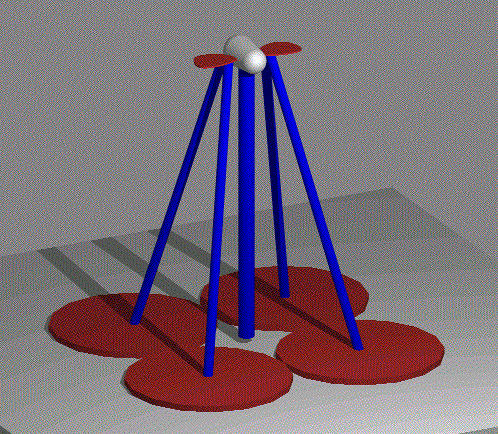
Wing drive system with 2 DOF per wing.
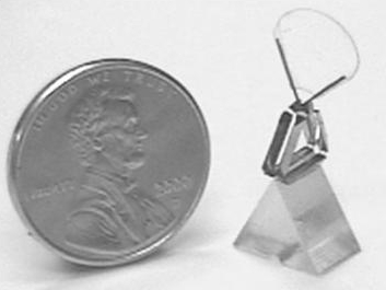
Preliminary version of steel wings, 10 mm in length, 100 micron thick made
using EDM process.
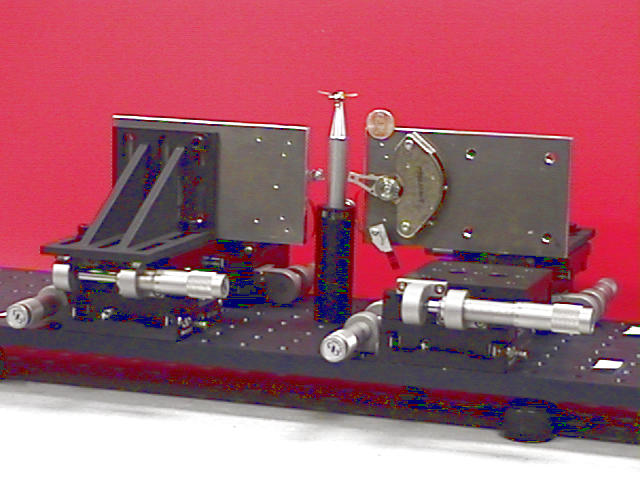
Drive system for wing mockup using voice coil actuators.
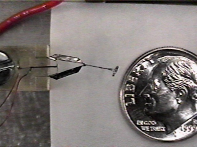
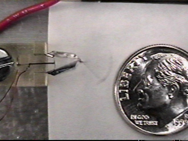
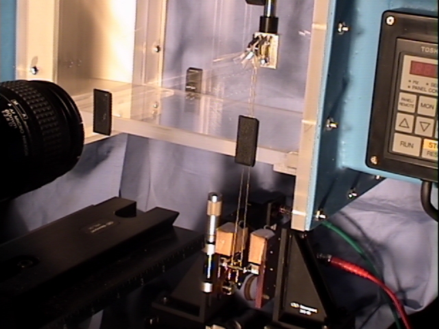
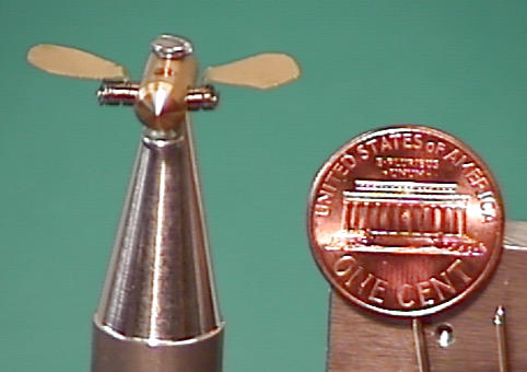
Positioning stages are used to easily change
actuator attachment direction and pre-loading. For clarity,
only 2 of 4 actuators are installed. Insect body and wings
are barely visible to left of penny.
Wings attached to mockup body using springs.
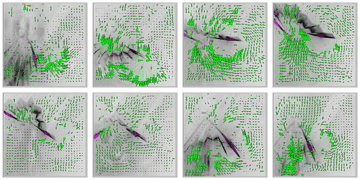
Flow image with wing driven at 30 Hz, stroke amplitude 45 degrees. Approximate peak wing tip speed of 1 m/s. Particle seeding is from right side of image. Hints of vortex formation at the wing tip can be seen. Wing drive using servo amp will be at 80 Hz and stroke amplitude greater than 90 degrees, and should give at least an order of magnitude greater fluid force.