CS 184: COMPUTER GRAPHICS
PREVIOUS
< - - - - > CS
184 HOME < - - - - > CURRENT
< - - - - > NEXT
Lecture #23 -- Mon 4/18/2011.
Question of the Day:
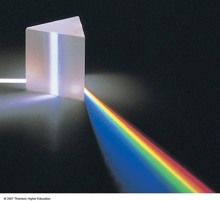
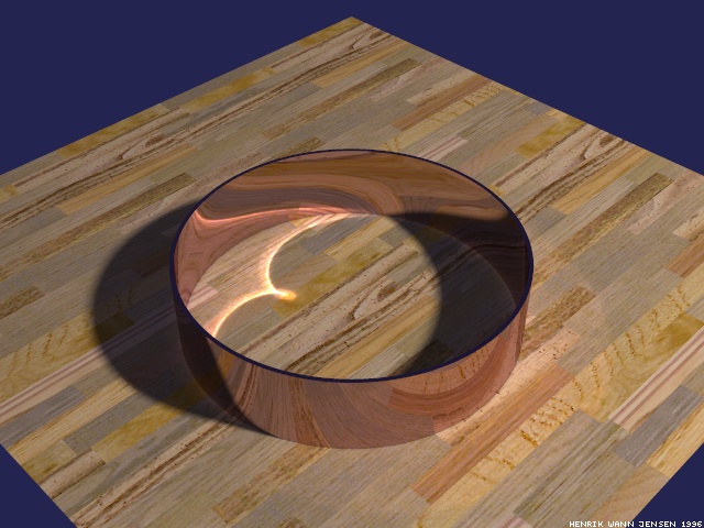
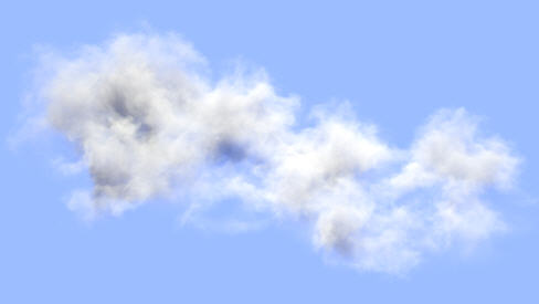
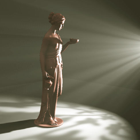
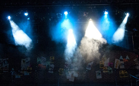
Why are the rendering paradigms discussed so far not good enough to render these scenes ?
What are the effects that we have not yet taken care of
? -- What might be a conceptual way to
deal with them ?


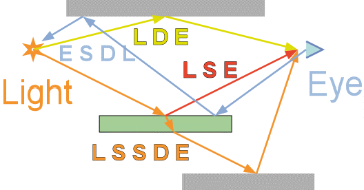
Characterizing the Types of Rendering Paths with Regular Expressions:
L = Path starts at or hits a light source
D = Path makes a diffuse bounce
S = Path makes a specular / refractive bounce
E = Path hits (or starts at) the eye
|
|
Ray Casting (review)
Rays are cast from the eye through all pixels and report their first
intersection in Scene. From these points of intersections, rays may be
cast towards all light sources to determine whether they are
illuminated by those sources or are shadowed by some obstacle.
Symbolically, these are the paths that are being investigated: E (S|D) L
Ray Tracing (review)
Rays are cast from the eye through all pixels. At intersections with
reflective or with transparent surfaces, secondary rays are initiated
in the reflected and refracted directions; these new rays are generated
in a recursive manner.
Symbolically, these are the paths that are being investigated: E S* (S|D) L
Cone Tracing
This was a (mostly unsuccessful) attempt to make ray-tracing more
efficient by exploiting coherence of near-by rays. Cone-shaped bundles
of rays are pursued jointly, with the expectation that they
would experience (for the most part) the same kind of surface
intersections, reflections, and shadowing. But for interesting scenes,
this is typically not true, and the book-keeping becomes prohibitive.
Beam Tracing
This
was another (not so successful) attempt to make ray-tracing more
efficient by exploiting coherence of near-by rays. In this case, the
rays that are traced together form pyramids with polygonal cross
sections corresponding to the shape of individual faces or the spaces
left between them. Again, the various rays in a bundle will typically
encounter different situations and thus become dissimilar very quickly.
Classical Rendering Pipeline (review)
In a loose analogy, this can
be understood as a one-step "beam-casting" procedure. The pyramids
corresponding to individual faces in the scene, with the eye as the
pyramid tip are cast into the z-buffer and enhanced with some lighting
effects such as Gouraud shading or Phong shading.
Path Tracing
This is an exhaustive (inefficient), un-biased, statistical approach to
ray-casting that also generates secondary rays on diffuse surfaces.
These secondary rays are emitted in a statistical manner based on the BRDF
(Bidirectional reflectance distribution function) at the intersection
point with a surface. (More likely directions of reflection are sampled
more frequently.)
Symbolically, these are the paths that are being investigated: E (S|D)* L
Photon Tracing
This is also an exhaustive (inefficient), statistical approach to deal
with all forms of illumination in an unbiased way. It simulates
realistic photon behavior by using an
adapted ray tracing method that sends rays
from all light sources. Each ray keeps
bouncing around until one of three things occurs: (a) it leaves the
rendering scene; (b) it hits the eye or camera; (c) it has been
absorbed by one of the surface intersections or reduced in its radiance
value (probability of existence of the photon) below some appropriate
threshold.
Symbolically, these are the paths that are being investigated: L (S|D)* E
Metropolis Light Transport
The procedure constructs paths from the eye to a light source using bidirectional path tracing,
then constructs slight modifications to the path. Some careful
statistical calculation (the Metropolis algorithm) is used to compute
the appropriate distribution of brightness over the image. Once a path has been found from a light to the eye, the algorithm can
then explore nearby paths; thus difficult-to-find light paths can be
explored more thoroughly for a given number of simulated photons.
Metropolis Light Transport is an unbiased method that converges to a
solution of the rendering equation quicker than other unbiased
algorithms such as Path Tracing or Photon Tracing.
Deals with the ambient lighting coming from the "sky."
Assumes a hemispherical sky-dome of uniform brightness.
Calculates for each surface point in the scene a quick approximation of
what fraction of this sky-dome can be seen, and assigns a corresponding
brightness.
Tries to answer the question "How do the photons from the light
source(s) travel around the scene?" in a more efficient manner than
Photon Tracing by exploiting coherence and relying on conservation of
energy. In the simplest case we assume all the surfaces are
perfectly diffuse reflectors.
Thus the apparent brightness of a surface is independent of viewer
position.
However, large (flat) polygons can still have non-uniform brightness
because of non-uniform illumination.
We now consider indirect illumination by other illuminated and
diffusely
reflecting surfaces.
For this, we break up large surfaces into small flat polygons (patches)
over which we can assume the brightness to be constant.
Once all the patches have been assigned their brightness (color) values,
we can render the scene from any viewpoint.
To calculate the amount of diffuse illumination that gets passed from
one patch to another, we need to know the form factor between them. This form factor describes how well the two patches can see
one another (depends on distance, relative orientation, occluders between
them).
Once we have determined all these purely geometrical form factors,
we can set up a system of p linear equations in the radiosity of the p patches.
Solving this system with a direct method (e.g. Gaussian elimination)
is not practical, if there are thousands or millions of patches.
But we can exploit the fact that most of the form factors are typically
zero, since many pairs of patches cannot send much light to each other.
Thus we can apply an iterative approach:
-- First consider only the light directly emitted by the active light sources.
-- Then add the light that results from only a single reflection on
any surface from the source lights.
-- Next add the light that has seen two reflections, and so on ...
-- The process is stopped locally whenever the additional contributions fall
below some desired level of accuracy.
Symbolically, these are the paths that are being investigated: L D* E
Two-Pass Method
One way to combine the best capabilities of radiosity-based rendering
(indirect lighting by diffuse-diffuse interreflections)
and of ray-tracing (specular reflections, translucency), is
to use a two-pass method.
The first pass is a radiosity-like algorithm that creates an approximate
global illumination solution.
In the second pass this approximation is rendered using an optimized
Monte Carlo ray tracer (statistical sampling).
This scheme works very well for modest scenes.
But for models with millions of polygons, procedural objects, and many
glossy reflections, the rendering costs rise steeply,
mainly because storing illumination within a tessellated representation
of the geometry uses too much memory.
This gives the best results for the amount of computational effort spent.
Symbolically, these are the paths that are being investigated: L (S|D)* E; E S* D.
Feedback on Course Projects
Keep it manageable! Focus on the key technical challenges.
Don't try to re-enact in only 3 weeks what took the computer graphics research community
or the video-game industry 10 years to develop!!
Revise and clarify your proposal by this Friday,
and show something on your project page that convinces us that you have started serious programming:
e.g., a rough geometry model of your main character, the overal test scene set-up for your fancy renderer,
a first track geometry for your
racing game, or a control polygon for your high-genus subdivision
surface...
Make sure that in two weeks you will have your basic scene set up and functional in a limited manner,
so that you have something worthwhile to write about in your progress report.
Reading Assignments:
Shirley: 2nd Ed: Ch.19.1 - 19.2; Ch.23
3rd Ed: Ch.20.1 - 20.2; Ch.24
CS 184 Course Project: Consult Project Page!
AS#11: Revise your project proposal; clarify technical challenges.
Show some evidence (a picture) that serious programming has started.
Every participant must have a link to a (shared) proposal on their web page.
Due Saturday April 23, 11pm (worth another 10% of project grade).
PREVIOUS
< - - - - > CS
184 HOME < - - - - > CURRENT
< - - - - > NEXT
Page Editor: Carlo
H. Séquin